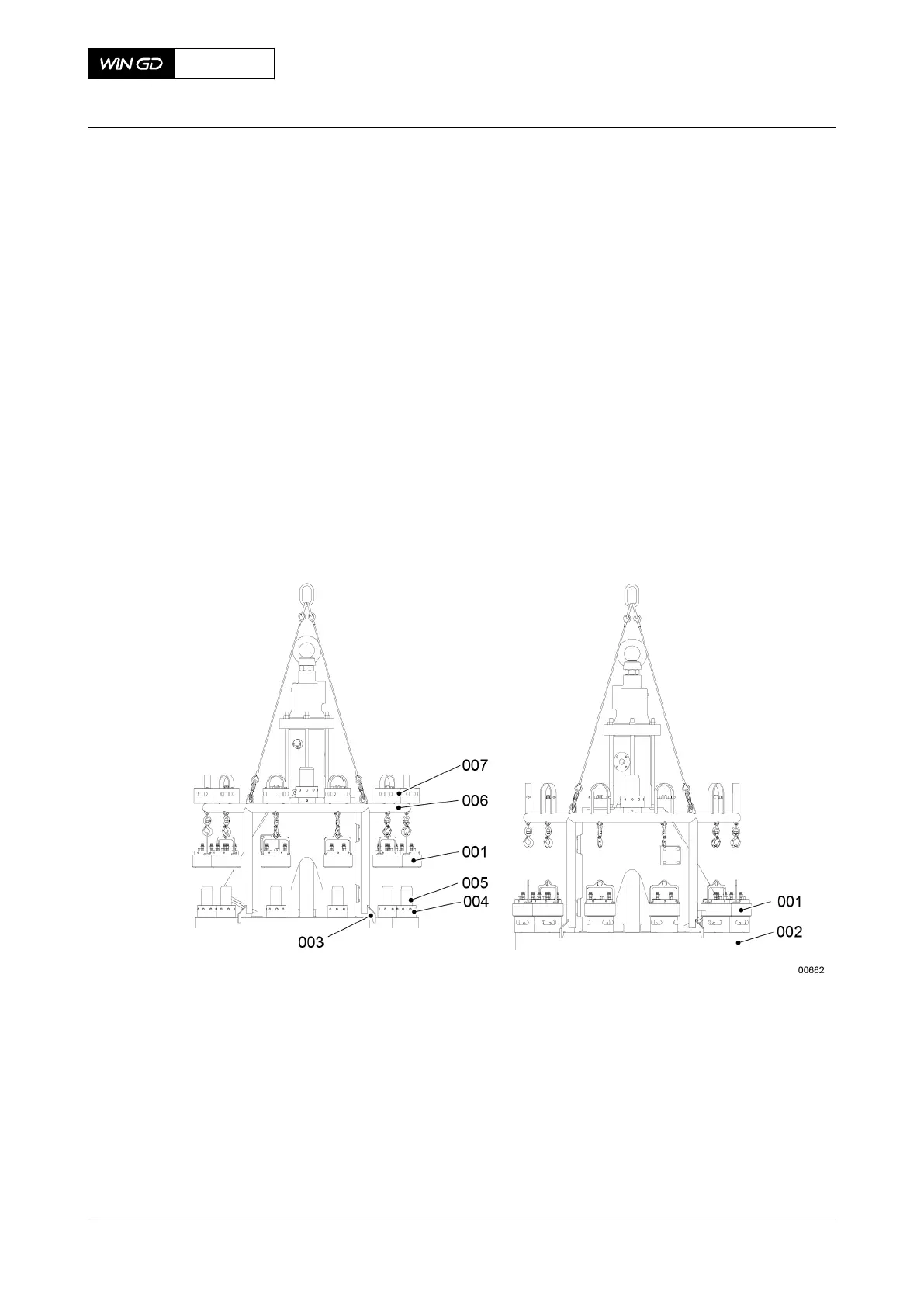
16 Put the round nuts (004, Figure 7-40) on the elastic studs (005).
17 Attach the engine room crane to the lifting tool (006).
18 Operate the engine room crane to move the lifting tool (006) and the pre-tensioners
above the cylinder cover (002).
19 Slowly lower the lifting tool (006) until the four plates (003) are on the cylinder cover
(002).
20 Connect the applicable flexible hose between each pre-tensioner.
21 Put the top and bottom parts (001, 007) of the pre-tensioners in position on the elastic
studs (005).
22 Put the pre-tensioners (001) on the round nuts (004).
23 Tighten the round nuts (004), refer to section 4.2 Tighten a round nut with a pre-
tensioner.
24 Remove the pre-tensioners (001).
25 Operate the engine room crane to remove the lifting tool (006).
Fig 7-40 Lifting tool - pre-tensioner (example)
26 Attach the cooling water pipe.
27 Connect all other connections removed before to the cylinder cover and to the exhaust
valve.
28 Install the hydraulic pipe, refer to the related procedure.
29 Install the HP fuel pipes, refer to the related procedure.
30 For a DF engine, install the pilot injection valves, refer to the related procedure.
31 Attach the cooling water pipe to the cylinder cover.
32 Install the expansion pipe, refer to the applicable steps in the related procedure.
33 Remove all tools and equipment from the work area.
X62DF
AA00-2708-00AAA-720A-A
Maintenance Manual Cylinder cover - install
Winterthur Gas & Diesel Ltd.
- 255 - Issue 002 2020-10