PROCEDURE
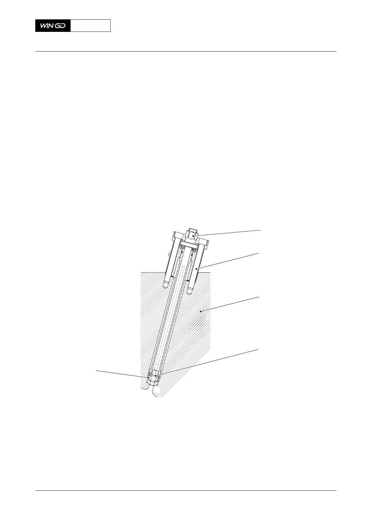
1 If the sensor (004, Figure 7-56) has been removed, install the sensor (004).
1.1 Move the sensor (004) with the cable through the relief valve.
1.2 Put the holder (005) to the sensor (004) and torque the sensor (004) to 15 Nm.
1.3 Put the holder (005) with the sensor (004) to the relief valve and torque the
holder (005) to 50 Nm.
2 Apply oil to the new O-rings.
3 Put the O-rings in the grooves of the relief valve.
4 Apply a thin layer of Never Seez to the contact surface of the relief valve.
5 Turn the spindle nut (001) to the upper position to get the open position.
6 Put the relief valve in position of the cylinder cover (003).
7 Apply a thin layer of Never Seez to the thread of the bolts (002).
8 Torque the bolts (002) to 50 Nm.
Fig 7-56 Relief valve combustion chamber
CLOSE UP
• None
X62DF
AA00-2740-00AAA-720A-A
Maintenance Manual Relief valve combustion chamber - install
Winterthur Gas & Diesel Ltd.
- 291 - Issue 002 2020-10