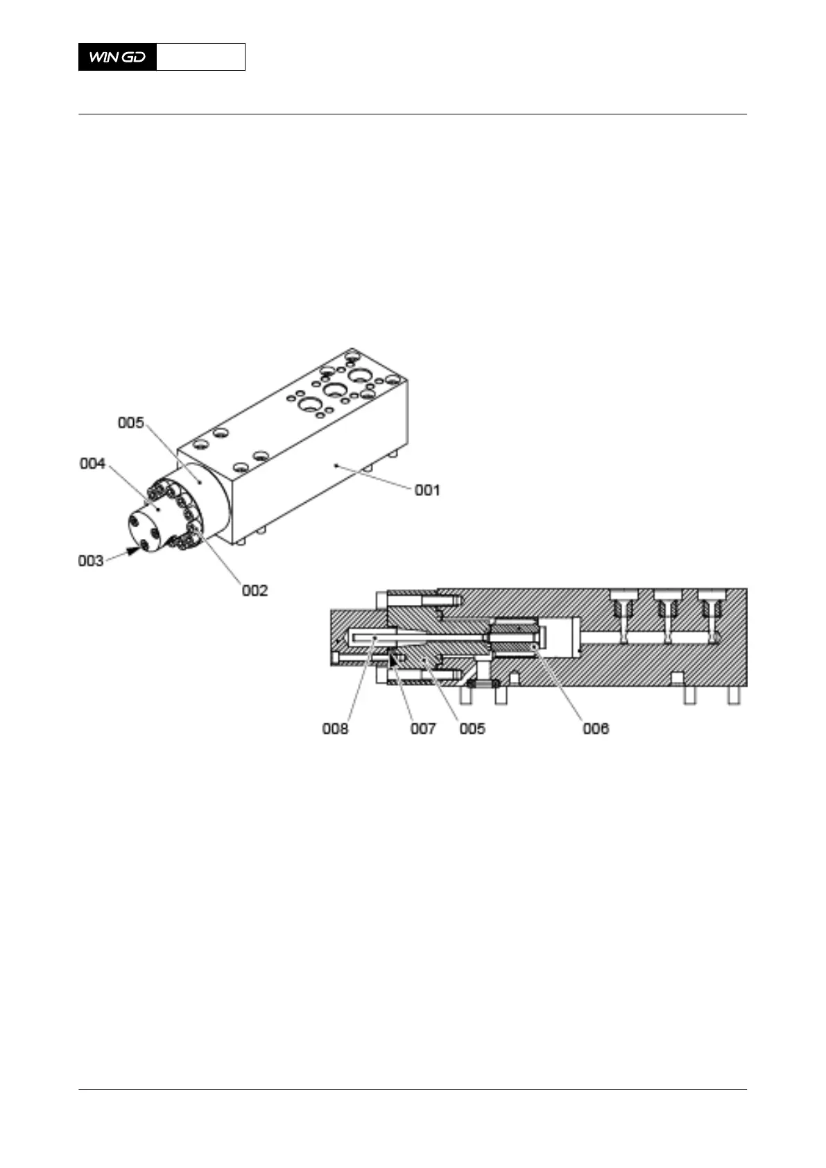
7 If it is necessary to disassemble the flange (005, Figure 10-31) and the piston rod (008),
do as follows:
7.1 Remove the Allen screws (003) and the cover (004) from the flange (005).
7.2 Remove and discard the O-ring (007).
7.3 Remove the Allen screws (002).
7.4 Remove carefully the flange (005) together with the piston rod (008) and the
piston (006).
Fig 10-31 Flow limiting valve - remove
CLOSE UP
• None
X62DF
AA00-5565-00AAA-520A-A
Maintenance Manual Flow limiting valve - remove
Winterthur Gas & Diesel Ltd.
- 606 - Issue 002 2020-10