PROCEDURE
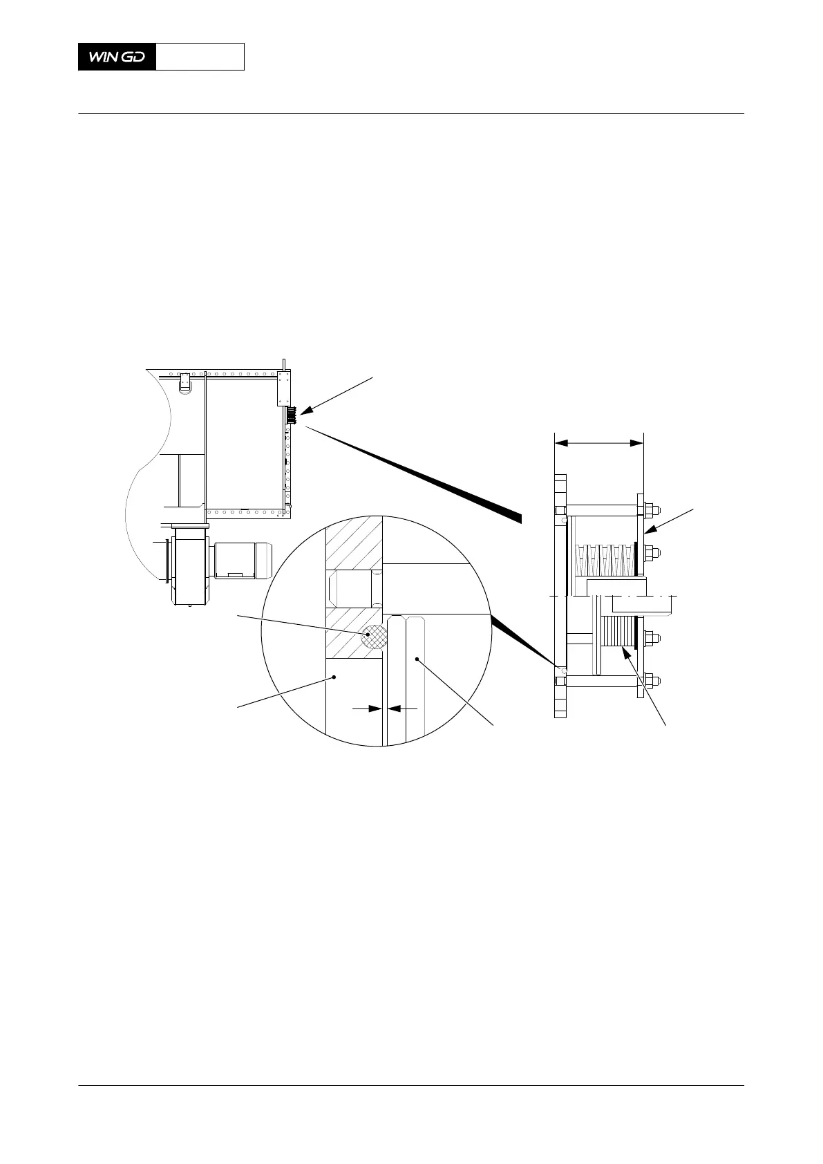
1 Do a visual check for damage and corrosion. If necessary, replace the relief valve (001,
Figure 11-3).
2 Make sure that there is a clearance (Y) between the flange (004) and the seal plate
(003), thus the O-ring (005) is serviceable.
3 Make sure that the distance X is 133 mm, thus the pressure of the disc springs (002) is
sufficient.
Fig 11-3 Relief valve
X
Y
001
001
002
004
003
005
00863
CLOSE UP
• None
X62DF
AA00-6420-00AAA-360A-A
Maintenance Manual Scavenge air receiver - do a check of the relief valve
Winterthur Gas & Diesel Ltd.
- 629 - Issue 002 2020-10