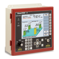
1128600 SmartPAC 2 with WPC 2000 Integration User Manual
2-70 Installation
Setting Up High-speed Version of SmartPAC 2 with WPC 2000
If you have a standard SmartPAC 2 and wish to change the system to a high-speed version
(1600 SPM maximum), you will need to order SmartPAC 2 firmware with the high-speed
option. Contact Wintriss Tech. Support for details. When you receive the new firmware,
perform the following steps:
1. Install SmartPAC 2 firmware with the high-speed option according to the instructions in
Appendix D.
2. Locate jumper J102 on the SmartPAC 2 board (see Figure 2-25, page 2-51), and move the
jumper from the pins at the LOW setting to the pins at the HIGH setting.
3. Locate jumpers J125 and J126 on the WPC 2000 Main Processor board (see Figure 2-14,
page 2-28), and move the jumpers from the pins at the LO setting to the pins at the HI
setting.
Wiring a Remote Reset Switch
If you would like to be able to reset the SmartPAC 2 and WPC 2000 from a location remote
from their enclosures, the SmartPAC 2 board provides a terminal (i.e., pin #249 on TB107)
for wiring a remote Reset switch.
Connect a wire from terminal #249 on TB107 on the SmartPAC 2 board to a normally open
switch (see Figure 2-25, page 2-51, Table 2-25, below, and Figure 1 at the end of the manual).
Connect another wire from the switch to terminal #250 on TB107. SmartPAC 2 and WPC
2000 are reset with a momentary connection to ground.
Wiring a Sensor-Disabled Output (Optional)
You can wire a Sensor-disabled Output such as a warning light to a customer-supplied solid-
state relay to warn personnel that the die protection capability, if installed, is disabled.
Connect the positive input wire from your 12Vdc solid-state relay to terminal #302 (Relay
Power) on TB553 on the DiProPAC board (see Figure 2-29, page 2-58 and Figure 9 at the
back of the manual). Connect the negative input wire from the relay to terminal #306
(Auxiliary 1) on TB553. You cannot use more than 8 mA for your relay.
Wintriss recommends that you wire the Remote Reset switch to SmartPAC 2 rather than to WPC
2000. A Reset switch wired to WPC 2000 can reset only WPC 2000 faults. The same switch wired
to SmartPAC 2 can reset faults for both controls.
Table 2-25. Remote Reset Switch Wiring Connections
SmartPAC 2 Board, TB107
Pin # Signal
249 Remote Reset input
250 Ground

 Loading...