04/2016
4-8
Phaser 4600/4620/4622 Printer Service Manual
REP 1.5
Revised
4 Repairs and Adjustments
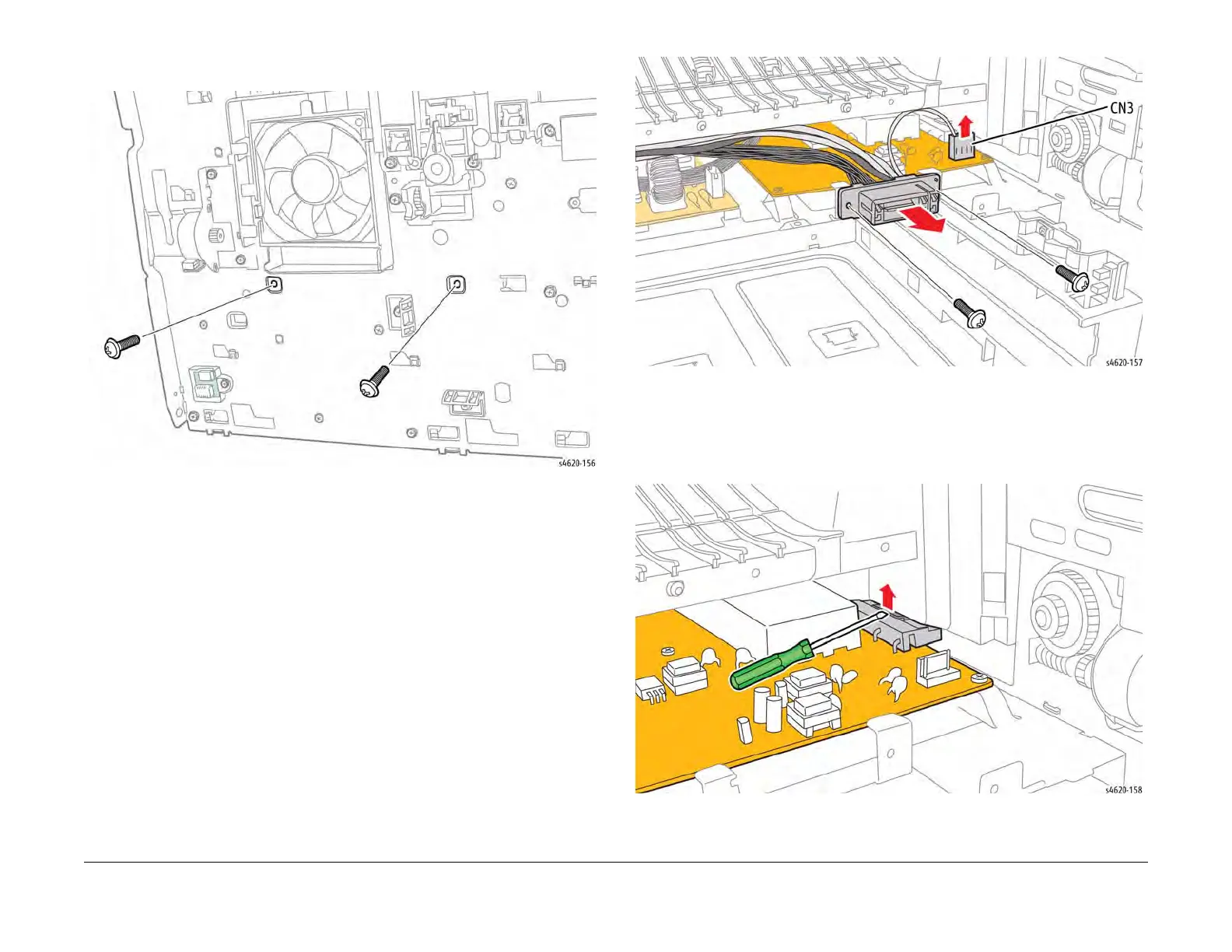
13. Remove 2 screws (metal) that secure the left side of the power supply tray to the chassis,
Figure 4.
Figure 4 Remove the left side power supply tray screws
14. Remove 2 screws (shank, metal) that secure the Fuser connector to the power supply
tray, Figure 5.
15. Disconnect CN3 from the HVPS and move the Fuser harness to the side, Figure 5.
Figure 5 Remove the Fuser connector
16. Pull the power supply tray out of the chassis to access CN2 through the SMPS Fan duct,
Figure 6.
17. Disconnect CN2 from the HVPS using a small screwdriver to release the connector hook,
Figure 6.
Figure 6 Disconnect the drum bias voltage connector