Theory of Operation 2-11
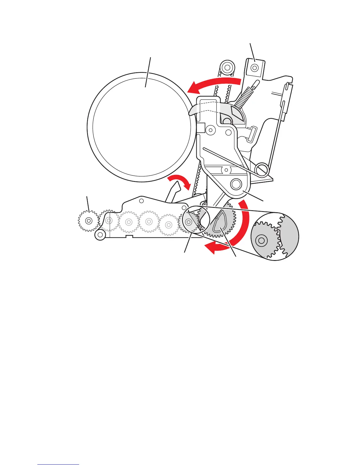
In the print position (0 degrees), the printhead is forward and rests against the right
and left head-to-drum buttons. The head-to-drum buttons define the space between
the jet stack and the drum. When the process drive is activated, it drives the drum
maintenance camshaft to engage the tilt gear train. The tilt cam tilts the printhead into
the print position. The cam is combined with a missing tooth gear that allows the cam
to be inactive in the print position, freeing the process drive to perform other printer
operations.
The cam has a latching mechanism to unlatch and latch the missing tooth gear to
engage the printhead tilt drive train. The cam’s latching mechanism also holds the tilt
gear in place. A leaf spring applies constant pressure to engage the gear when the
latching mechanism is released. The arm of the latching mechanism is inside the
frame; the rest is visible, outside the frame. Arrows located on the latching
mechanism and on the frame indicate when the printhead is in print position. When
the arrows on the latching mechanism and frame align, the printhead is in the print
position and the tilt gear disengages from the process drive. Phaser 8500/8550
printers have a new solenoid that is actuated and deactuated when the tilt cam gear
rotates to the respective engaged and disengaged positions.
Drum
Printhead
Tilt Gear
Tilt Gear (Engaged)
Printhead Restraint
s8500-015
DM Cam Gear

 Loading...