4.3 Wiring the Power Supply to the SERVOPACK
4.3.3 Power ON Sequence
4-15
3.
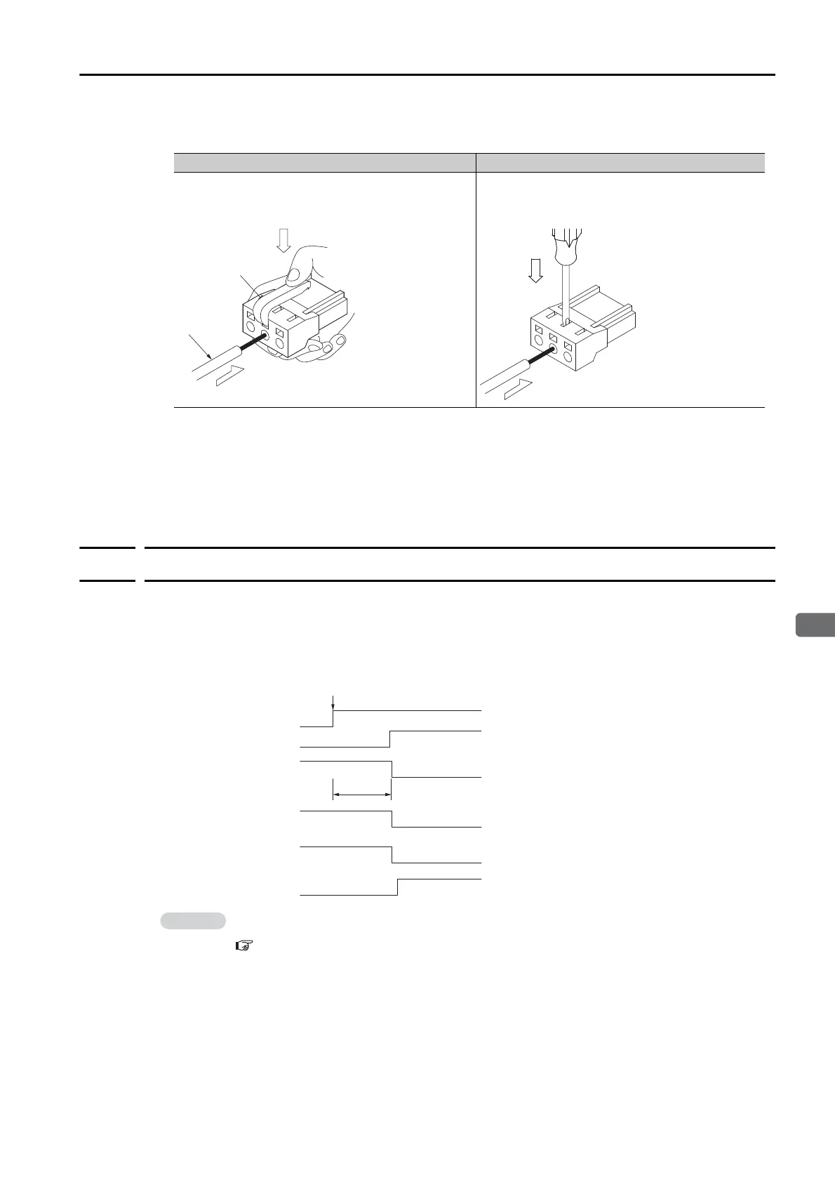
Open the wire insertion hole on the terminal connector with the tool. There are the fol-
lowing two ways to open the insertion hole. Use either method.
4.
Insert the conductor into the wire insertion hole. Then, remove the Spring Opener or flat-
blade screwdriver.
5.
Make all other connections in the same way.
6.
When you have completed wiring, attach the connectors to the SERVOPACK.
4.3.3
Power ON Sequence
Consider the following points when you design the power ON sequence.
• The ALM (Servo Alarm) signal is output for up to five seconds when the control power supply
is turned ON. Take this into consideration when you design the power ON sequence, and
turn ON the main circuit power supply to the SERVOPACK when the ALM signal is OFF (alarm
cleared).
Using a Spring Opener
Using a Flat-blade Screwdriver
Open the insertion hole with the Spring Opener as
shown in the figure.
Firmly insert a flat-blade screwdriver into the
screwdriver insertion hole to open the wire inser-
tion hole.
Wire
Spring Opener
If the servo ON state cannot be achieved by turning ON the /S_ON signal, the /S_RDY signal
is not ON. Check the status of the /S_RDY signal. Refer to the following section for details.
/S-RDY (Servo Ready) Signal on page 6-8
Up to 5.0 s
Control power supply
Main circuit power supply
ALM (Servo Alarm)
signal
/S_RDY (Servo Ready)
signal
/S-ON (Servo ON)
signal
Alarm cleared.Alarm
ONOFF
ONOFF
Motor power status
Power supplied.Power not supplied.
ONOFF
ONOFF
Power ON

 Loading...


