4.4 Wiring Servomotors
4.4.1 Terminal Symbols and Terminal Names
4-26
4.4
Wiring Servomotors
4.4.1
Termi n a l S ymbo l s and Ter m i n al Nam e s
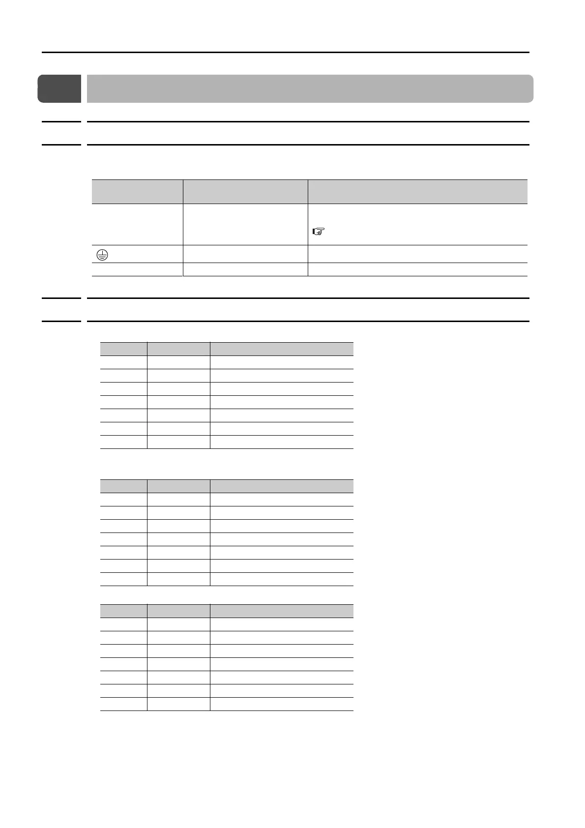
The SERVOPACK terminals or connectors that are required to connect the SERVOPACK to a
Servomotor are given below.
4.4.2
Pin Arrangement of Encoder Connector (CN2)
• When Using a Rotary Servomotor
* No wiring is required for an incremental encoder or a batteryless absolute encoder.
• When Using a Direct Drive Servomotor
• When Using a Linear Servomotor
Terminal/Connector
Symbols
Terminal/Connector Name Remarks
U, V, and W Servomotor terminals
Refer to the following section for the wiring proce-
dure.
4.3.2 Wiring Procedure for Main Circuit Connector on
page 4-14
Ground terminal
–
CN2 Encoder connector
–
Pin No. Signal Function
1 PG5V Encoder power supply +5 V
2 PG0V Encoder power supply 0 V
3BAT (+)* Battery for absolute encoder (+)
4BAT (-)* Battery for absolute encoder (-)
5 PS Serial data (+)
6 /PS Serial data (-)
Shell Shield –
Pin No. Signal Function
1 PG5V Encoder power supply +5 V
2 PG0V Encoder power supply 0 V
3 – – (Do not use.)
4 – – (Do not use.)
5 PS Serial data (+)
6 /PS Serial data (-)
Shell Shield –
Pin No. Signal Function
1 PG5V Linear encoder power supply +5 V
2 PG0V Linear encoder power supply 0 V
3 – – (Do not use.)
4 – – (Do not use.)
5 PS Serial data (+)
6 /PS Serial data (-)
Shell Shield –

 Loading...


