6.1 I/O Signals
6.1.2 Output Signals
6-7
/SEL0 to /SEL7 (Program Step Selection Inputs) Signals
These signals specify the program step.
You can change the settings for the /SEL0 to /SEL7 signals with PnB06 to PnB0D. If you
change the settings for the /SEL0 to /SEL4 signals, set the /MODE 0/1 signal to ON (closed)
(Mode 0). If you change the settings for the /SEL5 to /SEL7 signals, the setting of the /MODE
0/1 signal is irrelevant.
6.1.2
Output Signals
ALM (Servo Alarm) Signal
This signal is output when the SERVOPACK detects an error.
Alarm Code (/ALO1 to /ALO3) Signals
The ALO1 to ALO3 (Alarm Code) signals report alarms and warnings that occur in the SERVO-
PACK. Use the alarm code output signals as required to display the contents of the alarm at the
host controller (e.g., HMI).
Refer to the following sections for details on the alarm codes.
15.2.1 List of Alarms on page 15-5
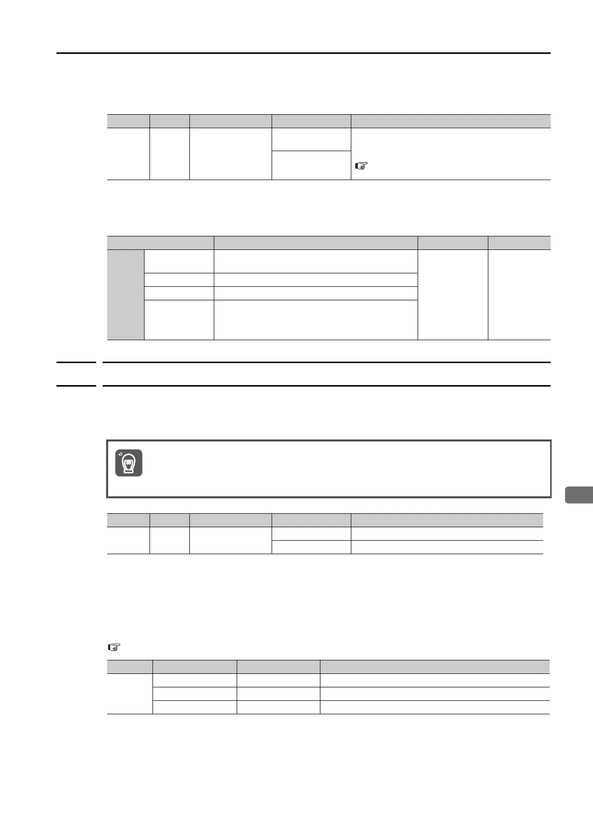
Typ e Signal Pin No. Signal Status Meaning
Input
/SEL0
to
/SEL7
CN11-9, -11,
-13 to -18
ON (closed)
These signals specify the program step number
at which to start program table operation. Refer
to the following section for details.
Input Signals Related to Program Table Opera-
tion on page 13-11
OFF (open)
Parameter Meaning When Enabled Classification
PnB06
PnB07
PnB08
PnB09
PnB0A
PnB0B
PnB0C
PnB0D
0000h
(default setting)
The /SEL signal is active when ON (closed).
After restart Setup
0001h The /SEL signal is active when OFF (open).
0002h The /SEL signal is always active.
0003h The /SEL signal is always inactive.
Configure an external circuit so that this alarm output turns OFF the main circuit power supply to
the SERVOPACK whenever an error occurs.
Typ e Signal Connector Pin No. Signal Status Meaning
Output ALM CN1-3 and CN1-4
ON (closed) Normal SERVOPACK status
OFF (open) SERVOPACK alarm
Typ e Signal Name Pin No. Description
Output
/ALO1 CN1-1, -2 Alarm code output
/ALO2 CN1-23, -24 Alarm code output
/ALO3 CN1-25, -26 Alarm code output

 Loading...


