10.3 Parameter Settings for Fully-Closed Loop Control
10.3.1 Control Block Diagram for Fully-Closed Loop Control
10-5
10
Fully-Closed Loop Control
10.3
Parameter Settings for Fully-Closed Loop Control
This section describes the parameter settings that are related to fully-closed loop control.
10.3.1
Control Block Diagram for Fully-Closed Loop Control
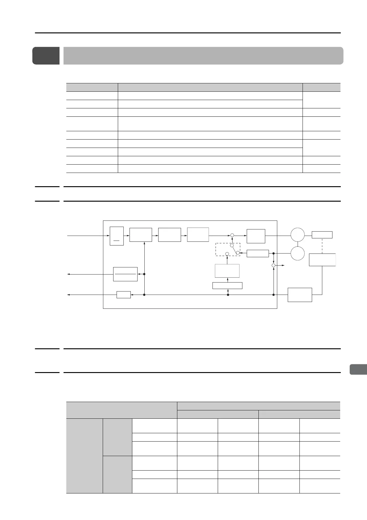
The control block diagram for fully-closed loop control is provided below.
* The connected device depends on the type of external encoder.
Note: You can use either an incremental or an absolute encoder. If you use an absolute encoder, set Pn002 to
n.1 (Use the absolute encoder as an incremental encoder).
10.3.2
Setting the Motor Direction and the Machine Movement
Direction
You must set the motor direction and the machine movement direction. To perform fully-closed
loop control, you must set the motor rotation direction with both Pn000 = n.X (Direction
Selection) and Pn002 = n.X (External Encoder Usage).
Parameter to Set Setting Reference
Pn000 = n.X Motor direction
page 10-5
Pn002 = n.X External encoder usage method
Pn20A Number of external scale pitches
page 10-6
Pn281
Encoder divided pulse output signals (PAO, PBO, and PCO) from the
SERVOPACK
page 10-7
Pn20E and Pn210 Electronic gear ratio
page 5-41
Pn51B Motor-Load Position Deviation Overflow Detection Level
page 10-9
Pn52A Multiplier for fully-closed rotation
Pn006/Pn007 Analog monitor signal
page 10-10
Pn22A = n.X Speed feedback method during fully-closed loop control
page 10-10
−
ENC
*
A.d10
Pn22A
Pn20E
Pn210
A
B
+
Pn281
1
SERVOPACK
Deviation
counter
Position
control loop
Unit conversion
Pn20A
Speed
feedback
Speed
loop
Speed conversion
Alarm
detection
Unit conversion
Pn20A
Electronic gear
Divider
Speed conversion
Motor
External
encoder
Serial
conversion
Machine
Electronic
gear
Position reference
Position deviation
Encoder divided
pulse output
Parameter
Pn002 = n.X (External Encoder Usage)
n.1 n.3
Pn000
=n.X
(Direction
Selection)
n.0
Reference
direction
Forward
reference
Reverse
reference
Forward
reference
Reverse
reference
Motor direction CCW CW CCW CW
External
encoder
Forward
movement
Reverse
movement
Reverse
movement
Forward
movement
n.1
Reference
direction
Forward
reference
Reverse
reference
Forward
reference
Reverse
reference
Motor direction CW CCW CW CCW
External
encoder
Reverse
movement
Forward
movement
Forward
movement
Reverse
movement

 Loading...


