14.6 Echoback Response Time
14-9
14
Operation with Serial Command Communications
14.6
Echoback Response Time
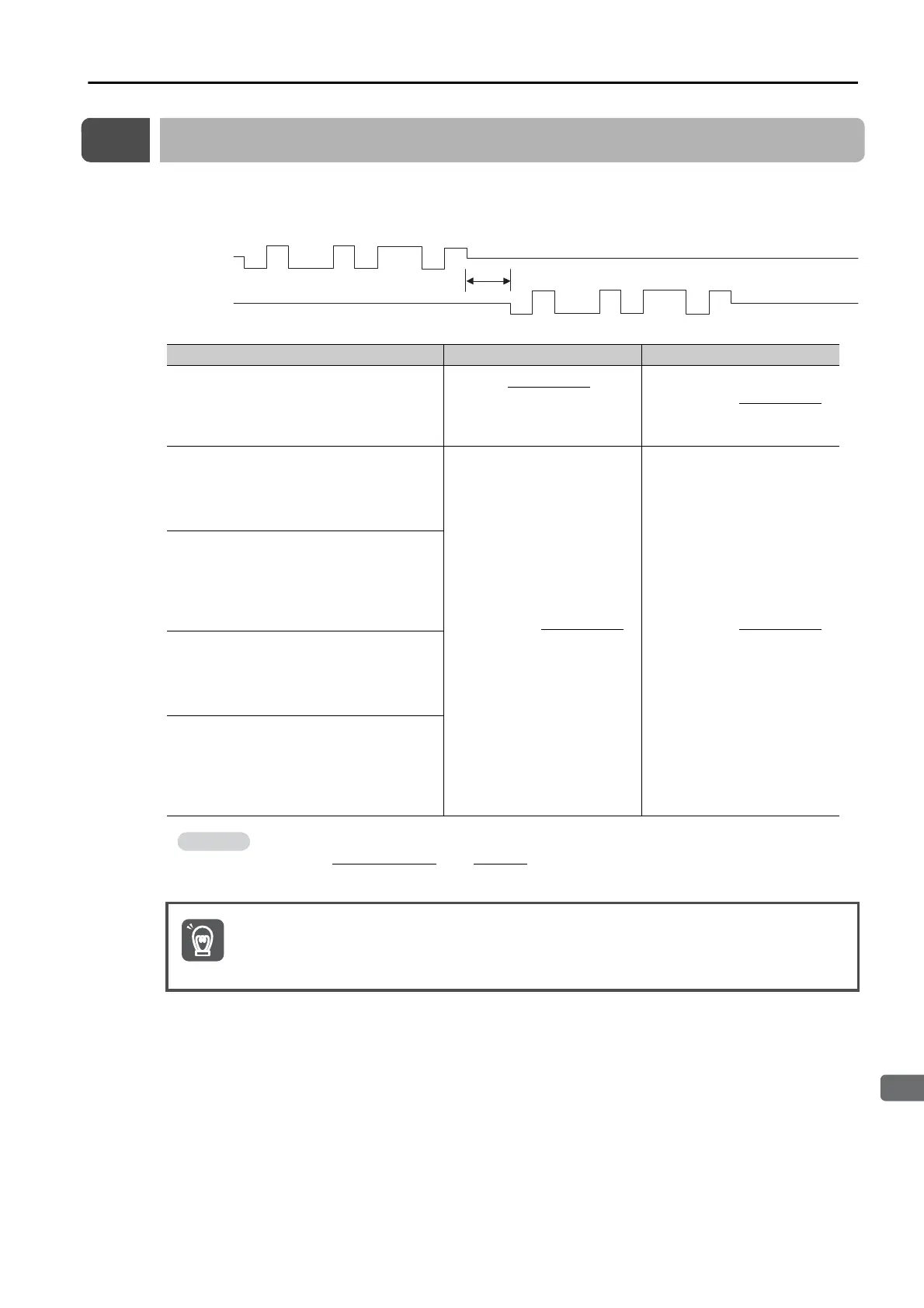
The following diagram shows the response time from the command transmission until the
echoback.
PnB00 (Protocol) Settings t
E
Min. t
E
Max.
0001h:
Full-duplex wiring is used for communica-
tions method.
Echoback is performed for each character.
(Centered at the command
stop bit)
0003h:
Half-duplex wiring is used for communica-
tions method.
CR is used as the delimiter.
Echoback is performed for each character.
0004h:
Half-duplex wiring is used for communica-
tions method.
CR is used as the delimiter.
Echoback is performed for each com-
mand.
0006h:
Half-duplex wiring is used for communica-
tions method.
CRLF is used as the delimiter.
Echoback is performed for each character.
0007h:
Half-duplex wiring is used for communica-
tions method.
CRLF is used as the delimiter.
Echoback is performed for each com-
mand.
For PnB00 = 0001h and PnB01 = 0000h (bit rate of 9,600 bps):
t
E
min = = -52 μs
When using half-duplex wiring, the host controller must set the line driver to high impedance
within the t
E
min. response time.
Start bit
High impedance
Stop bit
t
E
High impedance
Echoback
Command
−
Bit rate
×
2
1
=
−
9600
×
2
1

 Loading...


