6.5 Encoder Divided Pulse Output
6.5.1 Encoder Divided Pulse Output Signals
6-15
6.5
Encoder Divided Pulse Output
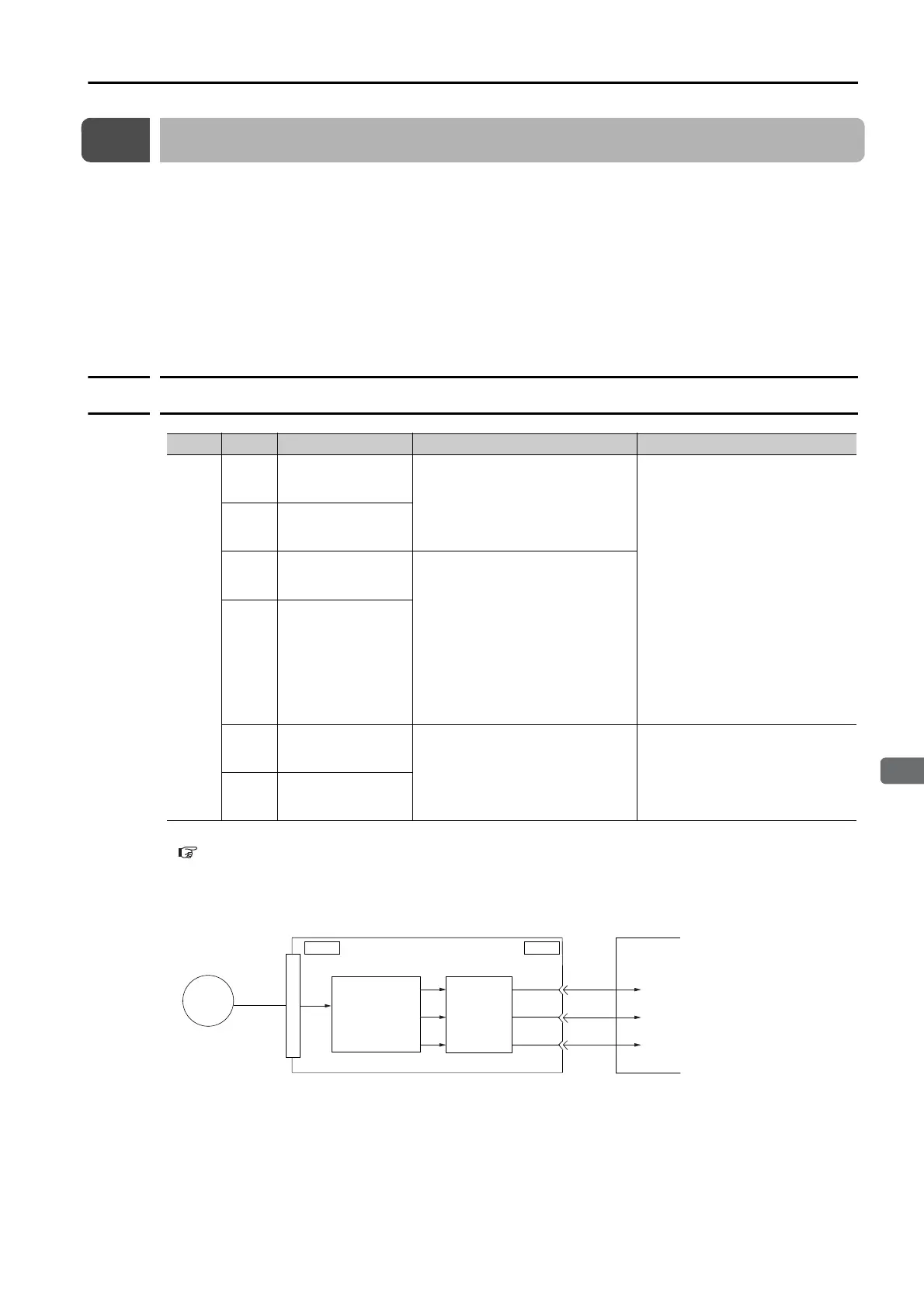
The encoder divided pulse output is a signal that is output from the encoder and processed
inside the SERVOPACK. It is then output externally in the form of two phase pulse signals
(phases A and B) with a 90° phase differential. At the host controller, it can be used as the posi-
tion feedback.
The encoder signals can be used to monitor the servomotor’s speed and position. However,
the INDEXER Module manages the servomotor’s speed and position so it is not necessary to
use the encoder signals to monitor the speed and position from the host controller.
The following table describes the signals and output phase forms.
6.5.1
Encoder Divided Pulse Output Signals
* Refer to the following section for information on the origin within one encoder rotation.
Relation between Renishaw PLC Incremental Linear Encoders and Encoder Output Pulse Signal from the SER-
VOPACK When Using a RGS20 Scale and RGH22B Sensor Head on page 6-16
• Rotary Servomotor
Typ e Signal Connector Pin No. Name Remarks
Output
PAO CN1-17
Encoder Divided Pulse Output,
Phase A
• Rotary Servomotors
These encoder divided pulse
output pins output the number
of pulses per Servomotor reso-
lution that is set in Pn212
(Number of Encoder Output
Pulses). The phase difference
between phase A and phase B
is an electric angle of 90°.
• Linear Servomotors
These encoder divided pulse
output pins output pulses at the
resolution that is set in Pn281
(Encoder Output Resolution).
The phase difference between
phase A and phase B is an
electric angle of 90°.
/PAO CN1-18
PBO CN1-19
Encoder Divided Pulse Output,
Phase B
/PBO CN1-20
PCO CN1-21
Encoder Divided Pulse Output,
Phase C*
These pins output one pulse
every Servomotor rotation.
/PCO CN1-22
ENC
CN1CN2
PAO
PBO
PCO
(Pn212)
SERVOPACK
Host controller
Serial
data
Conversion of
serial data to
pulses
Dividing
circuit

 Loading...


