4.5 I/O Signal Connections
4.5.3 I/O Circuits
4-41
4.5.3
I/O Circuits
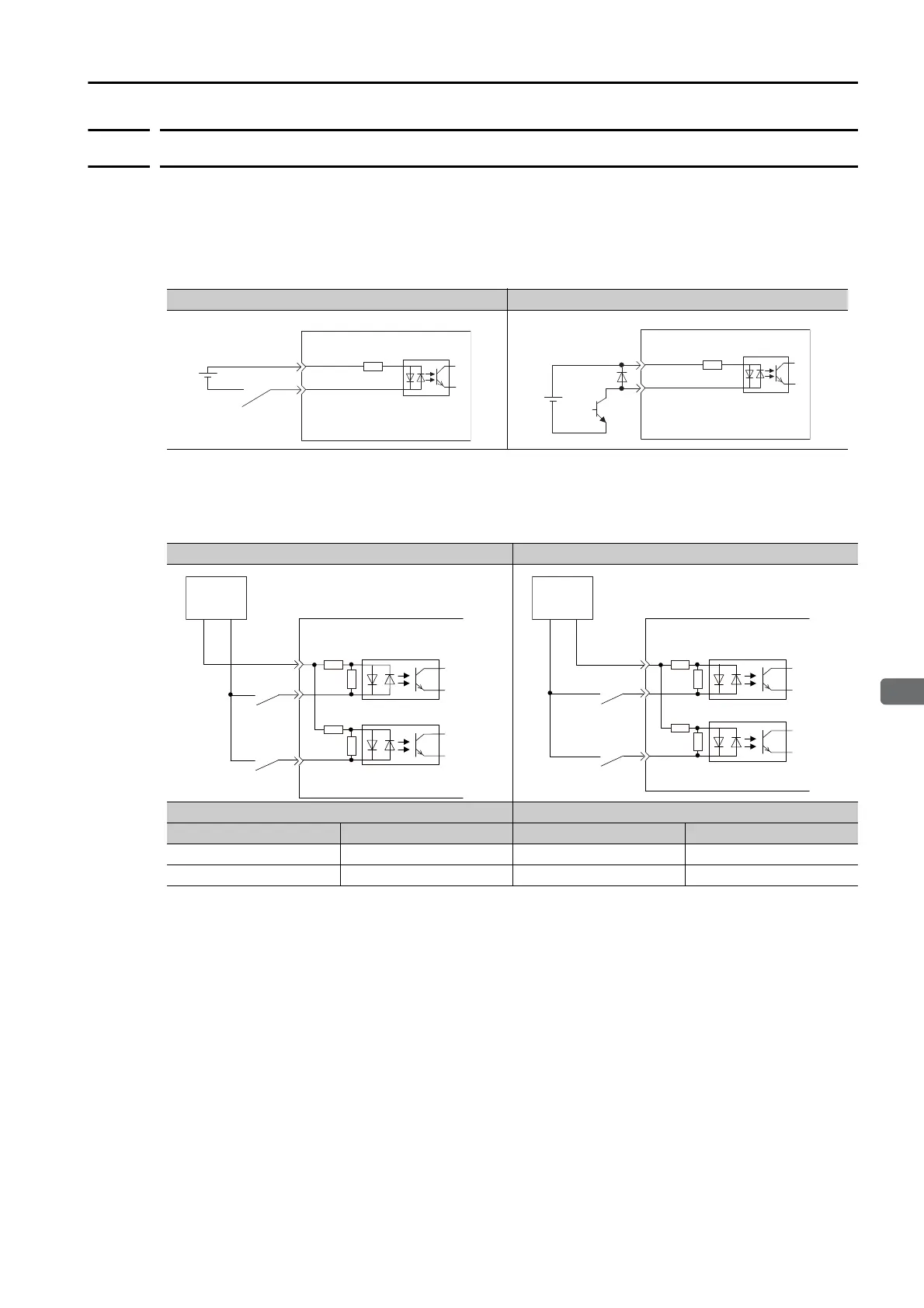
Sequence Input Circuits
Photocoupler Input Circuits
This section describes CN1 connector terminals 6 to 13.
Note: The 24-VDC external power supply capacity must be 50 mA minimum.
The SERVOPACK input circuits use bidirectional photocouplers. Select either a sink circuit or
source circuit according to the specifications required by the machine.
Note: The connection examples in I/O Signal Wiring Examples on page 4-36 are for sink circuit connections.
Examples for Relay Circuits Examples for Open-Collector Circuits
Sink Circuits Source Circuits
Input Signal Polarity Input Signal Polarity
Photocoupler Internal Signal Level Photocoupler Internal Signal Level
ON Low level ON Low level
OFF High level OFF High level
4.7 kΩ
E.g., /DEC
SERVOPACK
24 VDC
+24VIN
24 VDC
4.7 kΩ
E.g., /DEC
SERVOPACK
+24VIN
SERVOPACK input side
Switch
Photocoupler
Internal
signal
level
Internal
signal
level
Photocoupler
Switch
24 V
+
−
SERVOPACK input side
24 V
+
−
Switch
Photocoupler
Internal
signal
level
Internal
signal
level
Photocoupler
Switch

 Loading...


