7.1 Flow of Trial Operation
7.1.2 Flow of Trial Operation for Linear Servomotors
7-3
7.1.2
Flow of Trial Operation for Linear Servomotors
The procedure for trial operation is given below.
• Preparations for Trial Operation
3
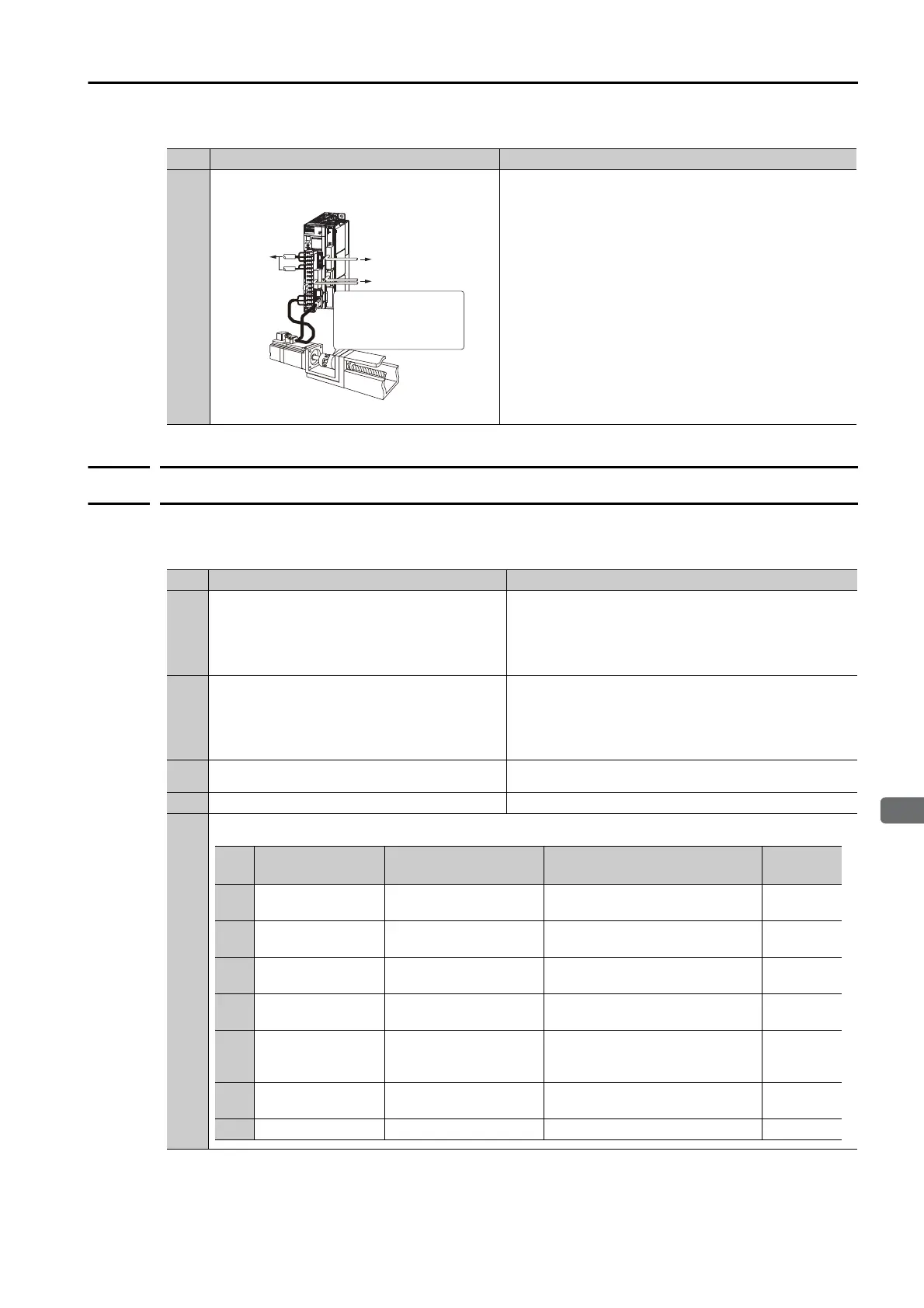
Trial Operation with the Servomotor Con-
nected to the Machine
7.5 Trial Operation with the Servomotor Connected to the
Machine on page 7-12
Continued from previous page.
Step
Meaning Reference
To power
supply
To host controller
Secure the motor ange to the
machine, and connect the
motor shaft to the load shaft
with a coupling or other means.
Step
Meaning Reference
1
Installation
Install the Servomotor and SERVOPACK
according to the installation conditions. First,
operation is checked with no load. Do not
connect the Servomotor to the machine.
Chapter 3 Installation
2
Wiring and Connections
Wire and connect the SERVOPACK. First,
Servomotor operation is checked without a
load. Do not connect the CN1 connector on
the SERVOPACK.
Chapter 4 Wiring and Connecting
3
Confirmations before Trial Operation
7.2 Inspections and Confirmations before Trial Operation
on page 7-6
4
Power ON −
5
Setting Parameters in the SERVOPACK
Continued on next page.
Step
No. of Parameter
to Set
Description Remarks Reference
5-1 Pn282 Linear Encoder Pitch
Set this parameter only if you are
using a Serial Converter Unit.
page 5-16
5-2 –
Writing Parameters to
the Linear Servomotor
Set this parameter only if you are
not using a Serial Converter Unit.
page 5-17
5-3 Pn080 = n.X
Motor Phase Sequence
Selection
–
page 5-21
5-4 Pn080 = n.X
Polarity Sensor Selec-
tion
–
page 5-23
5-5 – Polarity Detection
This step is necessary only for a
Linear Servomotor with a Polarity
Sensor.
page 5-24
5-6 PnB0F and PnB10
Overtravel Signal Allo-
cations
–
page 5-27
5-7 Pn483, Pn484 Force Control –
page 6-22

 Loading...


