9.3 Monitoring Machine Operation Status and Signal Waveforms
9.3.3 Using the Analog Monitors
9-10
9.3.3
Using the Analog Monitors
Connect a measuring instrument, such as a memory recorder, to the analog monitor connector
(CN5) on the SERVOPACK to monitor analog signal waveforms. The measuring instrument is
not provided by Yaskawa.
Refer to the following section for details on the connection.
4.8.3 Analog Monitor Connector (CN5) on page 4-48
Setting the Monitor Object
Use Pn006 = n.XX and Pn007 = n.XX (Analog Monitor 1 and 2 Signal Selections) to set
the items to monitor.
* Refer to the following section for details.
8.12.1 Automatic Gain Switching on page 8-64
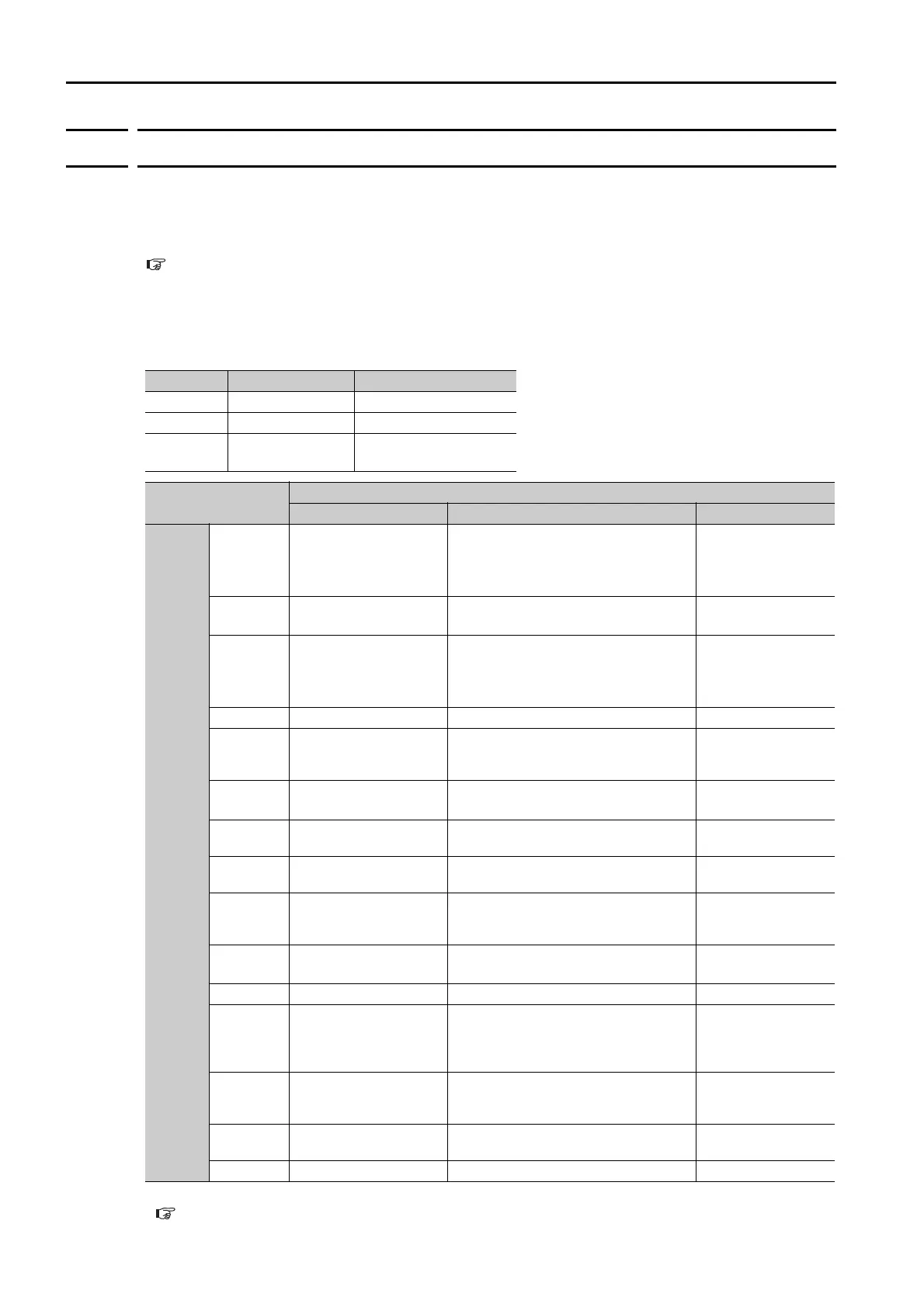
Line Color Signal Parameter Setting
White Analog monitor 1 Pn006 = n.XX
Red Analog monitor 2 Pn007 = n.XX
Black
(2 lines)
GND –
Parameter
Description
Monitor Signal Output Unit Remarks
Pn006
or
Pn007
n.00
(default
setting of
Pn007)
Motor Speed
• Rotary Servomotor: 1 V/1,000 min
-1
• Linear Servomotor: 1 V/1,000 mm/s
–
n.
01 Speed Reference
• Rotary Servomotor:1 V/1,000 min
-1
• Linear Servomotor:1 V/1,000 mm/s
–
n.02
(default
setting of
Pn006)
Torque Reference 1 V/100% rated torque –
n.
03 Position Deviation 0.05 V/Reference unit –
n.
04
Position Amplifier
Deviation
0.05 V/encoder pulse unit
Position deviation
after electronic gear
conversion
n.
05
Position Command
Speed
• Rotary Servomotor:1 V/1,000 min
-1
• Linear Servomotor:1 V/1,000 mm/s
–
n.
06
Reserved setting
(Do not use.)
––
n.
07
Motor - Load Position
Deviation
0.01 V/Reference unit –
n.
08 Positioning Completion
Positioning completed: 5 V
Positioning not completed: 0 V
Completion is indi-
cated by the output
voltage.
n.
09 Speed Feedforward
• Rotary Servomotor:1 V/1,000 min
-1
• Linear Servomotor:1 V/1,000 mm/s
–
n.0A Torque Feedforward 1 V/100% rated torque –
n.
0B Active Gain*
1st gain: 1 V
2nd gain: 2 V
The gain that is
active is indicated
by the output volt-
age.
n.0C
Completion of Position
Reference Distribution
Distribution completed: 5 V
Distribution not completed: 0 V
Completion is indi-
cated by the output
voltage.
n.
0D
External Encoder
Speed
1 V/1,000 min
-1
Value calculated at
the motor shaft
n.
10 Main Circuit DC Voltage 1 V/100 V (main circuit DC voltage) –

 Loading...


