4.3 Wiring the Power Supply to the SERVOPACK
4.3.4 Power Supply Wiring Diagrams
4-18
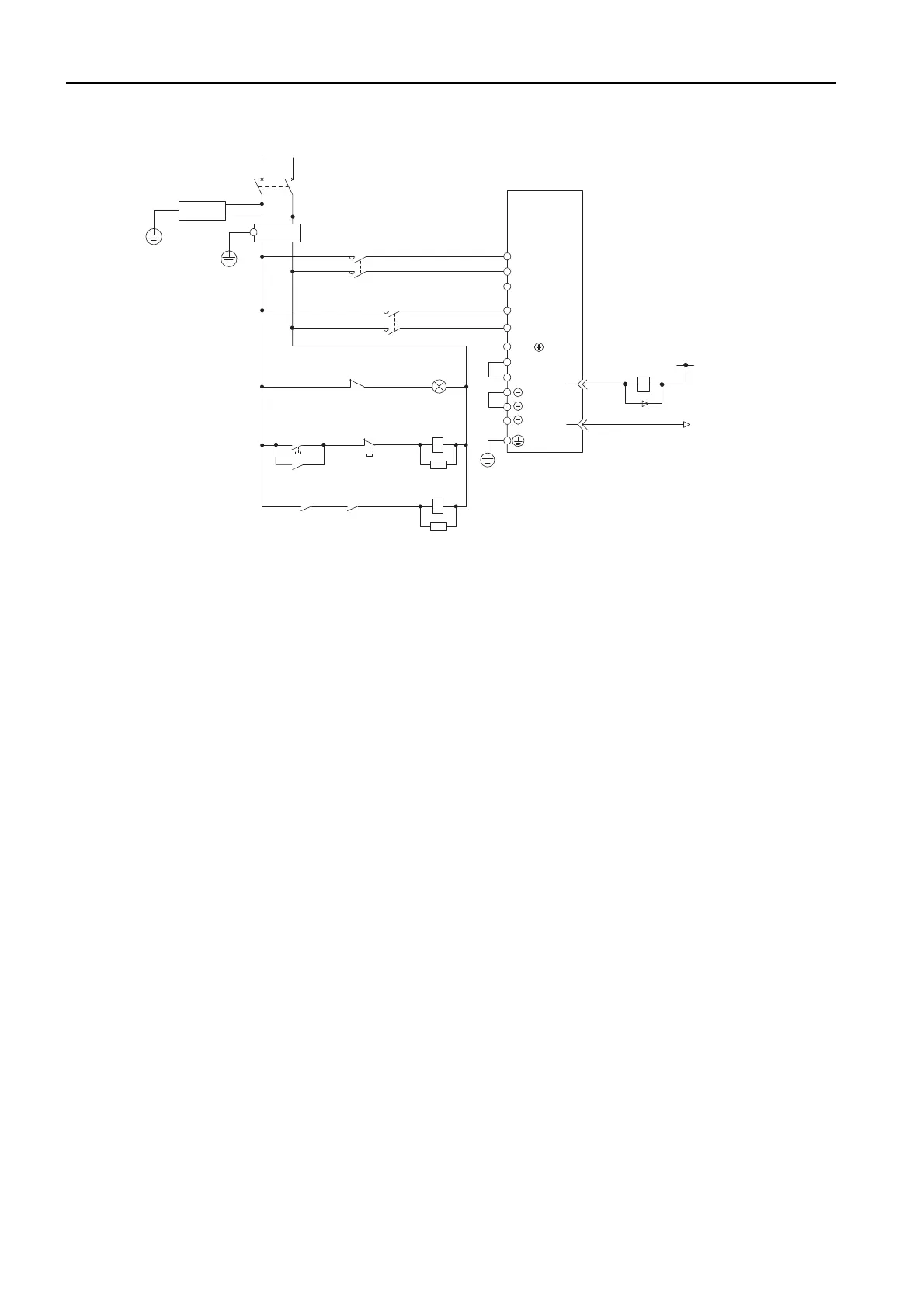
• Wiring Example for Single-Phase, 200-VAC Power Supply Input
* You do not have to connect B2 and B3 for the following models: SGD7S-R70A, SGD7S-R90A, SGD7S-
1R6A, and SGD7S-2R8A. Do not connect them.
2KM
L1
0 V
1Ry
+
−
3
4
1D
B2
B3
L2
CN1
1KM
L1C
L3
L2C
1QF
R
T
1FLT
+24 V
1
2
*
3SA
B1/
1PL
1KM
2KM
1SA
2SA
1KM
1Ry
1KM
ALM
ALM
1Ry
SERVOPACK
(For servo alarm
display)
Servo power
ON
Servo power
OFF
1QF: Molded-case circuit breaker
1FLT: Noise Filter
1KM: Magnetic Contactor
(for control power supply)
2KM: Magnetic Contactor
(for main circuit power supply)
1Ry: Relay
1PL: Indicator lamp
1SA: Surge Absorber
2SA: Surge Absorber
3SA: Surge Absorber
1D: Flywheel diode

 Loading...


