4.3 Wiring the Power Supply to the SERVOPACK
4.3.4 Power Supply Wiring Diagrams
4-20
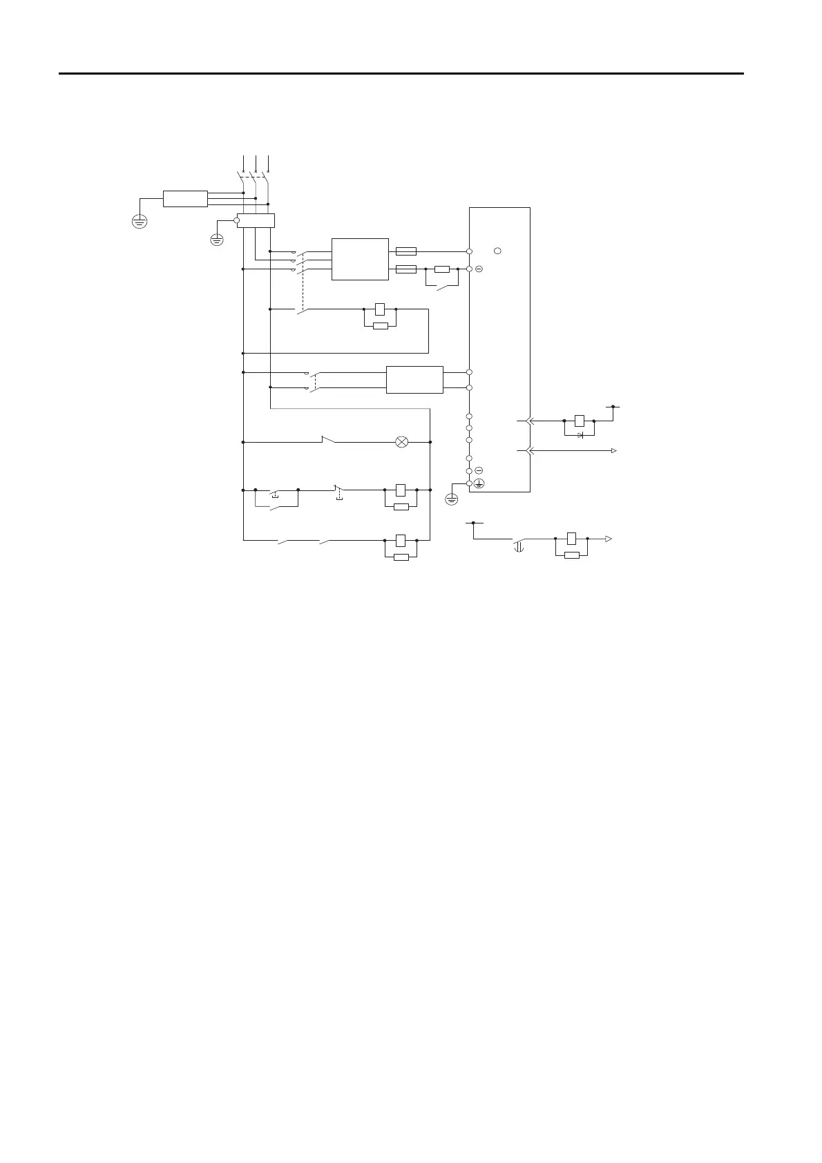
• Wiring Example for DC Power Supply Input: SGD7S-330A, -470A, -550A, -590A, and
-780A
1PL
1KM
2KM
1SA
2SA
L1C
L2C
B1/
2
+
1FU
2KM
0 V
1Ry
1D
+24 V
1KM
AC/DC
1QF
R
ST
3SA
+
3
4
CN1
1Ry
1KM
1Ry
1KM
ALM
ALM
1FLT
−
B2
1
L1
L2
L3
AC/DC
4SA
1TRy
2Ry
1R
2FU
+24 V
1TRy 0 V
5SA
2Ry
1SA: Surge Absorber
2SA: Surge Absorber
3SA: Surge Absorber
4SA: Surge Absorber
5SA: Surge Absorber
1D: Flywheel diode
1R: External inrush current
suppression resistor
SERVOPACK
(For servo alarm
display)
Servo power
ON
Servo power
OFF
1QF: Molded-case circuit breaker
1FLT: Noise Filter
1KM: Magnetic Contactor
(for control power supply)
2KM: Magnetic Contactor
(for main circuit power supply,
auxiliary contact)
1FU: Fuse, positive side
2FU: Fuse, negative side
1Ry: Relay
2Ry: Relay (for inrush current
suppression resistor switch)
1TRy: Timer relay
1PL: Indicator lamp

 Loading...


