4.4 Wiring Servomotors
4.4.3 Wiring the SERVOPACK to the Encoder
4-28
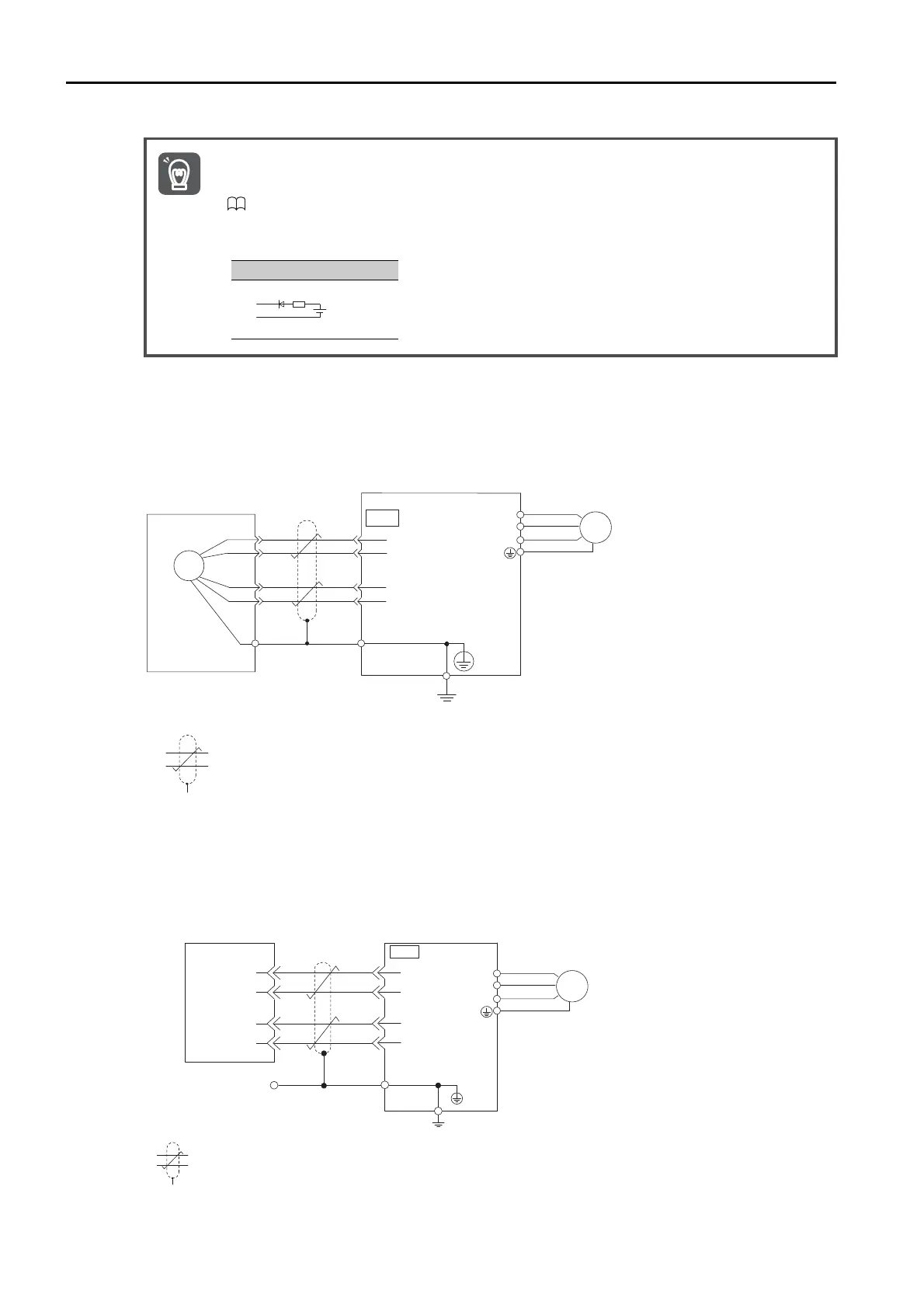
When Using an Incremental Encoder or Batteryless Abso-
lute Encoder
*1. The encoder pin numbers for wiring the connector depend on the Servomotor that you use.
*2. represents a shielded twisted-pair cable.
When Using an Absolute Linear Encoder
The wiring depends on the manufacturer of the linear encoder.
Connections to Linear Encoder from Mitutoyo Corporation
* represents a shielded twisted-pair cable.
• When Installing a Battery on the Encoder Cable
Use the Encoder Cable with a Battery Case that is specified by Yaskawa.
Refer to the following manual for details.
Σ-7-Series Peripheral Device Selection Manual (Manual No.: SIEP S800001 32)
• When Installing a Battery on the Host Controller
Insert a diode near the battery to prevent reverse current flow.
Important
Required Component Specifications
• Schottky Diode
Reverse Voltage: Vr ≥ 40 V
Forward Voltage: Vf ≤ 0.37 V
Reverse current: Ir ≤ 5 μA
Junction temperature: Tj ≥ 125℃
• Resistor
Resistance: 22
Ω
Tolerance: ±5% max.
Rated power: 0.25 W min.
Circuit Example
+
-
Battery
1
2
5
6
CN2
ENC
*2
*1
PS
/PS
PG5V
PG0V
U
V
W
M
(Shell)
Connector
shell
SERVOPACK
Shield
Incremental encoder
or batteryless
absolute encoder
*
PS
/PS
PG5V
PG0V
2
6
1
5
5
6
1
2
CN2
U
V
W
M
Absolute linear encoder
from Mitutoyo Corporation
Shield
Connector
shell
Connector
shell
SERVOPACK

 Loading...


