4.7 Connecting Safety Function Signals
4.7.2 I/O Circuits
4-47
Input (HWBB) Signal Specifications
The input (HWBB) signals have the following electrical characteristics.
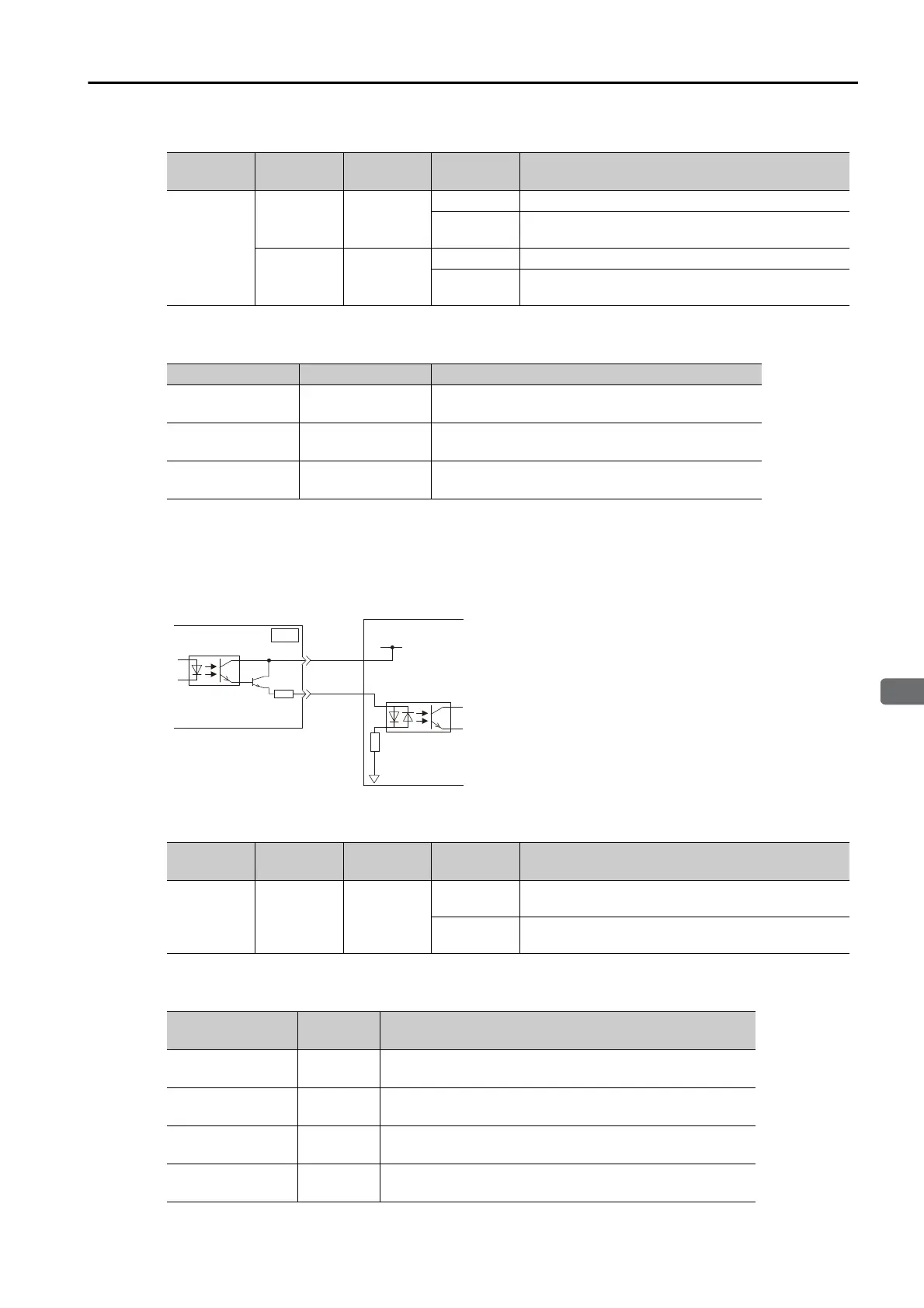
Diagnostic Output Circuits
The EDM1 output signal uses a source circuit. The following figure shows a connection exam-
ple.
EDM1 Output Signal Specifications
The electrical characteristics of the EDM1 signal are as follows:
Typ e Signal
Connector
Pin No.
Status Meaning
Inputs
/HWBB1
CN8-4
CN8-3
ON (closed) Does not activate the HWBB (normal operation).
OFF (open)
Activates the HWBB (motor current shut-OFF
request).
/HWBB2
CN8-6
CN8-5
ON (closed) Does not activate the HWBB (normal operation).
OFF (open)
Activates the HWBB (motor current shut-OFF
request).
Item Characteristics Remarks
Internal Imped-
ance
4.7 k
Ω −
Operating Voltage
Range
+24 V ±20% −
Maximum Delay
Time
8 ms
Time from /HWBB1 and /HWBB2 signals turning
OFF until HWBB is activated
Typ e Signal Pin No.
Output Sta-
tus
Meaning
Output EDM1
CN8-8
CN8-7
ON
Both the /HWBB1 and /HWBB2 signals are operat-
ing normally.
OFF
The /HWBB1 signal, the /HWBB2 signal, or both
are not operating.
Item
Character-
istics
Remarks
Maximum Allow-
able Voltage
30 VDC −
Maximum Allow-
able Current
50 mA DC −
Maximum ON
Voltage Drop
1.0 V
Voltage between EDM1+ and EDM1- when current is 50
mA
Maximum Delay
Time
8 ms
Time from a change in /HWBB1 or /HWBB2 until a change
in EDM1
24-V power supply
SERVOPACK
Host controller
EDM1+
EDM1-
0 V
8
7
CN8

 Loading...


