5.14 Electronic Gear Settings
5.14.1 Electronic Gear Ratio Settings
5-43
5
Basic Functions That Require Setting before Operation
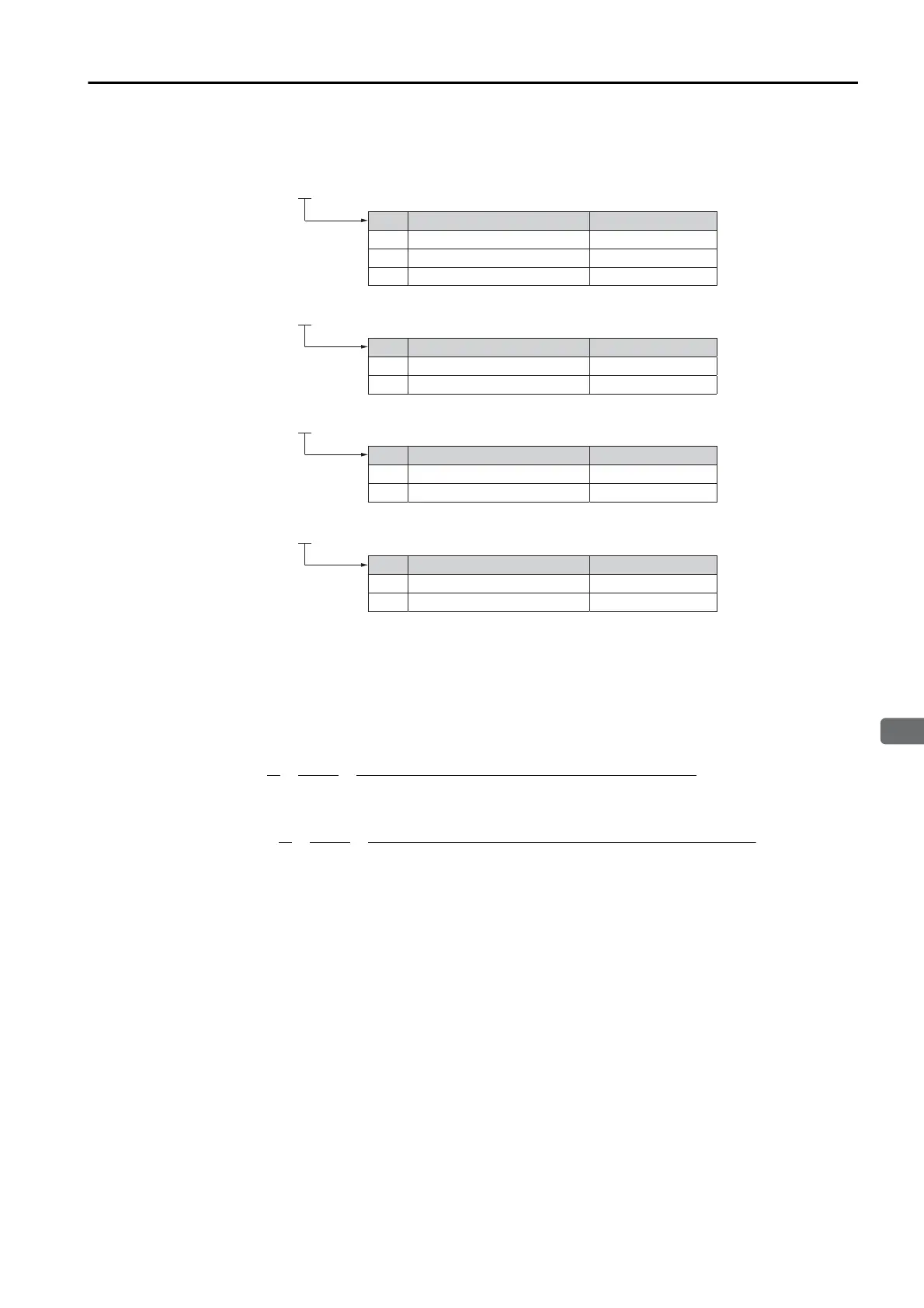
Encoder Resolution
You can check the encoder resolution in the Servomotor model number.
Linear Servomotors
You can calculate the settings for the electronic gear ratio with the following equation:
When Not Using a Serial Converter Unit
Use the following formula if the linear encoder and SERVOPACK are connected directly or if a
linear encoder that does not require a Serial Converter Unit is used.
When Using a Serial Converter Unit
6 16,777,216
SGM7J, SGM7A,
SGM7P, SGM7G -
7
16,777,216
F
16,777,216
SGMCS -
3
1,048,576
D
1,048,576
SGMCV -
E
4,194,304
I
4,194,304
SGM7E, SGM7F -
Code
Code
Code
Specication
Specication
24-bit multiturn absolute encoder
24-bit incremental encoder
20-bit single-turn absolute encoder
20-bit incremental encoder
Encoder Resolution
Encoder Resolution
Specication
22-bit single-turn absolute encoder
22-bit multiturn absolute encoder
Encoder Resolution
Code
Specication
24-bit batteryless multiturn absolute encoder
Encoder Resolution
7
16,777,216
F 16,777,216
24-bit multiturn absolute encoder
24-bit incremental encoder
Pn20E
Pn210
B
A
Electronic gear ratio
Travel distance per reference unit (reference units) × Linear encoder resolution
Linear encoder pitch (the value from the following table)
=
=
= =
Pn20E
Pn210
B
A
Electronic gear ratio
Travel distance per reference unit (reference units) × Resolution of the Serial Converter Unit
Linear encoder pitch (setting of Pn282)

 Loading...


