8.13 Manual Tuning
8.13.1 Tuning the Servo Gains
8-76
Torque Reference Filter
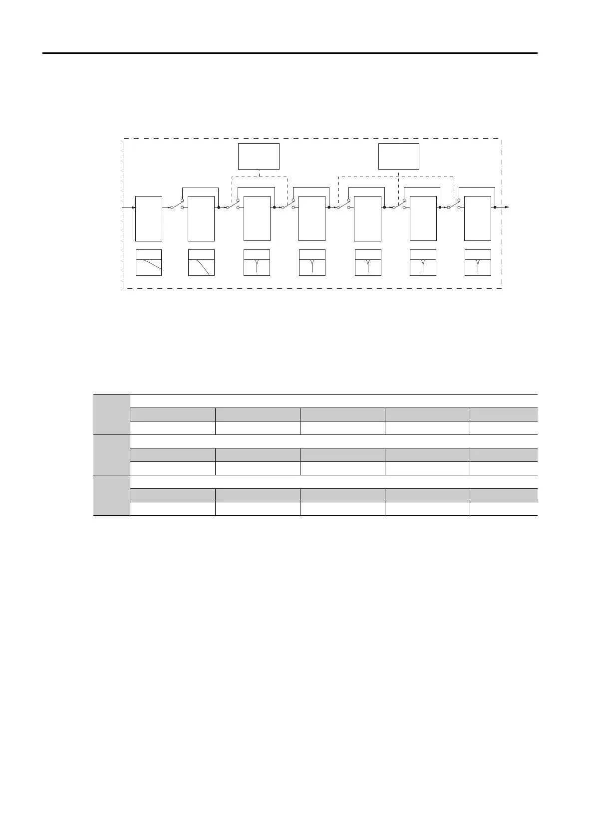
As shown in the following diagram, the torque reference filter contains a first order lag filter and
notch filters arranged in series, and each filter operates independently.
The notch filters can be enabled and disabled with Pn408 = n.XX and Pn416 = n.XXX.
* The second stage second torque reference filter is disabled when Pn40F is set to 5,000 (default setting) and it is
enabled when Pn40F is set to a value lower than 5,000.
Torque Reference Filter
If you suspect that machine vibration is being caused by the Servo Drive, try adjusting the
torque reference filter time constant. This may stop the vibration. The lower the value, the bet-
ter the control response characteristic will be, but there may be a limit depending on the
machine conditions.
* The filter is disabled if you set the parameter to 5,000.
Notch Filters
The notch filter can eliminate specific frequency elements generated by the vibration of sources
such as resonance of the shaft of a ball screw.
The notch filter puts a notch in the gain curve at the specific vibration frequency (called the
notch frequency). The frequency components near the notch frequency can be reduced or
removed with a notch filter.
Notch filters are set with three parameters for the notch filter frequency, notch filter Q value,
and notch filter depth. This section describes the notch filter Q value and notch filter depth.
• Notch filter Q Value
The setting of the notch filter Q value determines the width of the frequencies that are filtered
for the notch filter frequency. The width of the notch changes with the notch filter Q value. The
larger the notch filter Q value is, the steeper the notch is and the narrower the width of frequen-
cies that are filtered is.
Pn401
First Stage First Torque Reference Filter Time Constant
Setting Range Setting Unit Default Setting When Enabled Classification
0 to 65,535 0.01 ms 100 Immediately Tuning
Pn40F
Second Stage Second Torque Reference Filter Frequency
Setting Range Setting Unit Default Setting When Enabled Classification
100 to 5,000 1 Hz 5000* Immediately Tuning
Pn410
Second Stage Second Torque Reference Filter Q Value
Setting Range Setting Unit Default Setting When Enabled Classification
50 to 100 0.01 50 Immediately Tuning
Torque
reference
before lter
First
stage rst
torque
reference
lter:
Pn401
Second
stage second
torque
reference
lter:
Pn40F
Pn410
First
stage
notch lter:
Pn409
Pn40A
Pn40B
Second
stage
notch lter:
Pn40C
Pn40D
Pn40E
Torq ue
reference
after lter
Torque-Related
Function
Selections 1
Pn408
First order
lag lter
Second order
lag lter
*
Notch lter Notch lter Notch lter Notch lterNotch lter
Torque-Related
Function
Selections 2
Pn416
Third
stage
notch lter:
Pn417
Pn418
Pn419
Fourth
stage
notch lter:
Pn41A
Pn41B
Pn41C
Fifth
stage
notch lter:
Pn41D
Pn41E
Pn41F

 Loading...


