8.13 Manual Tuning
8.13.1 Tuning the Servo Gains
8-81
Model Following Control
You can use model following control to improve response characteristic and shorten position-
ing time. You can use model following control only with position control.
Normally, the parameters that are used for model following control are automatically set along
with the servo gains by executing autotuning or custom tuning. However, you must adjust them
manually in the following cases.
• When the tuning results for autotuning or custom tuning are not acceptable
• When you want to increase the response characteristic higher than that achieved by the tun-
ing results for autotuning or custom tuning
• When you want to determine the servo gains and model following control parameters yourself
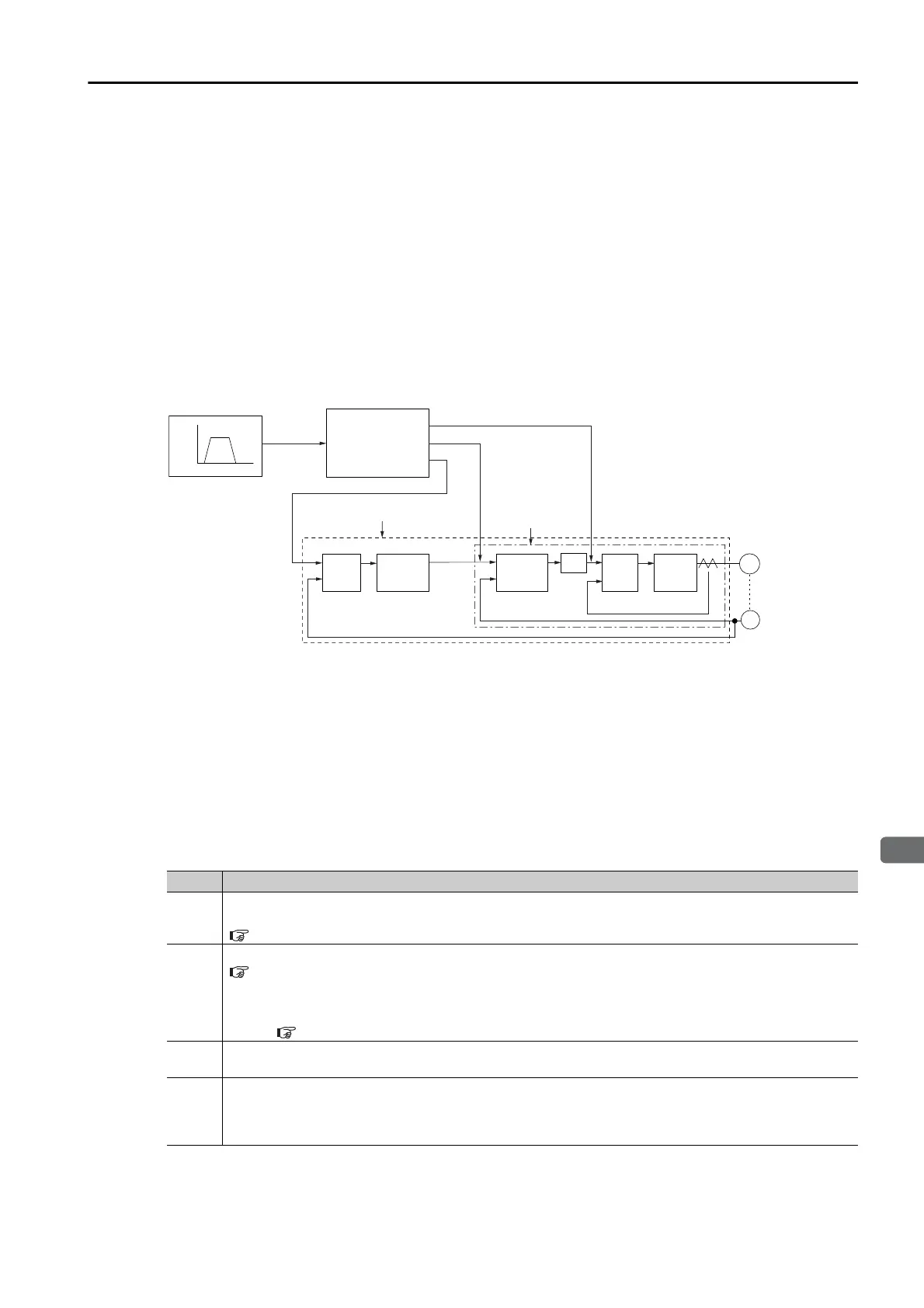
The block diagram for model following control is provided below.
Manual Tuning Procedure
Use the following tuning procedure for using model following control.
Step Description
1
Friction compensation must also be used. Set the friction compensation parameters. Refer to the
following section for the setting procedure.
8.12.2 Friction Compensation on page 8-67
2
Adjust the servo gains. Refer to the following section for an example procedure.
Tuning Procedure Example on page 8-74
Note: 1. Set the moment of inertia ratio (Pn103) as accurately as possible.
2. Refer to the guidelines for manually tuning the servo gains and set a stable gain for the position loop gain
(Pn102).
Guidelines for Manually Tuning Servo Gains on page 8-79
3
Increase the model following control gain (Pn141) as much as possible within the range in which
overshooting and vibration do not occur.
4
If overshooting occurs or if the response is different for forward and reverse operation, fine-tune
model following control with the following settings: model following control bias in the forward direc-
tion (Pn143), model following control bias in the reverse direction (Pn144), and model following con-
trol speed feedforward compensation (Pn147).
Model following
control
mKp, mVFF, mTFF
+
M
PG
+
+
Tf
Speed
Speed pattern
Time
Movement
reference
Torque feedforward
Speed control loop
Servomotor
Power
converter
Current
control
section
Speed loop
Speed control
section
Kv and Ti
Speed
reference
Position
loop gain
Kp
Deviation
counter
Position loop
Current loop
Encoder
Kp: Position loop gain (Pn102)
Kv: Speed loop gain (Pn100)
Ti: Speed loop integral time constant (Pn101)
Tf: First stage rst torque reference lter time constant (Pn401)
mKp: Model following control gain (Pn141)
Speed
feedforward
mTFF: Model following control bias in the forward direction (Pn143)
Model following control bias in the reverse direction (Pn144)
mVFF: Model following control speed feedforward compensation (Pn147)
Position control loop

 Loading...


