15.2 Alarm Displays
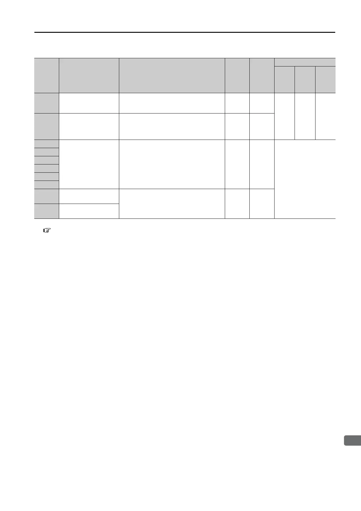
15.2.1 List of Alarms
15-11
A.F10
Power Supply Line
Open Phase
The voltage was low for more than one
second for phase R, S, or T when the
main power supply was ON.
Gr.2 Yes
HLH
A.F50
Servomotor Main Cir-
cuit Cable Disconnec-
tion
The Servomotor did not operate or power
was not supplied to the Servomotor even
though the /S-ON signal was input when
the Servomotor was ready to receive it.
Gr.1 Yes
FL-1
*2
System Alarm
An internal program error occurred in the
SERVOPACK.
–No
Invalid
FL-2
*2
FL-3
*2
FL-4
*2
FL-5
*2
FL-6
*2
CPF00
Digital Operator Com-
munications Error 1
Communications were not possible
between the Digital Operator (model:
JUSP-OP05A-1-E) and the SERVOPACK
(e.g., a CPU error occurred).
–No
CPF01
Digital Operator Com-
munications Error 2
*1. Refer to the following section for details.
15.2.3 INDEXER Module Alarm Displays and Troubleshooting on page 15-44
*2. These alarms are not stored in the alarm history. They are only displayed on the panel display.
Continued from previous page.
Alarm
Number
Alarm Name Alarm Meaning
Servo-
motor
Stop-
ping
Method
Alarm
Reset
Possi-
ble?
Alarm Code Output
/ALO1 /ALO2 /ALO3

 Loading...


