2.1 Ratings and Specifications
2.1.4 Specifications
2-9
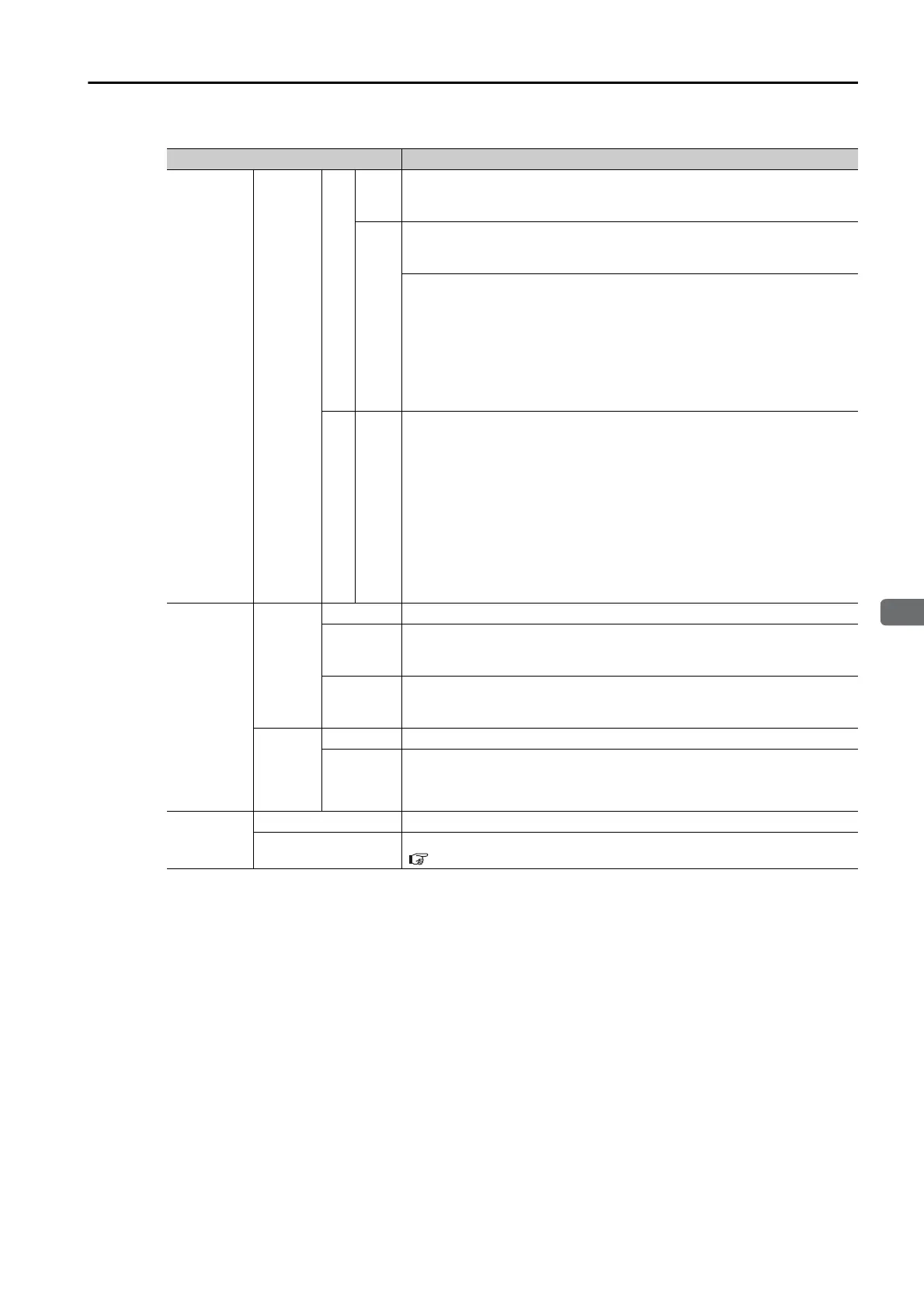
I/O Signals
Sequence
Output
Signals
SERVOPACK
Fixed
Out-
puts
Allowable voltage range: 5 VDC to 30 VDC
Number of output points: 1
Output signal: ALM (Servo Alarm Output) signal
Output Signals for Which
Allocations Can Be Changed
Allowable voltage range: 5 VDC to 30 VDC
Number of output points: 3
(A photocoupler output (isolated) is used.)
Output signals:
• /WARN (Warning Output) signal
• /BK (Brake Output) signal
• /S-RDY (Servo Ready Output) signal
• /ALO1, /ALO2, and /ALO3 (Alarm Code Output) signals
Signal allocations and positive or negative logic can be changed in the
parameters.
INDEXER Module
Fixed
Out-
puts
Allowable voltage range: 5 VDC to 30 VDC
Number of output points: 9
Output signals:
• /INPOSITION (Positioning Completion Output) signal
• /POUT0 (Programmable Output 0) signal
• /POUT1 (Programmable Output 1) signal
• /POUT2 (Programmable Output 2) signal
• /POUT3 (Programmable Output 3) signal
• /POUT4 (Programmable Output 4) signal
• /POUT5 (Programmable Output 5) signal
• /POUT6 (Programmable Output 6) signal
• /POUT7 (Programmable Output 7) signal
Communi-
cations
Digital
Opera-
tor Com-
municati
ons
(CN3)
Interfaces Digital Operator (JUSP-OP05A-1-E)
1:N
Communi-
cations
Up to N = 15 stations possible for RS-422A port
Axis
Address
Setting
Set with parameters.
USB
Commu-
nica-
tions
(CN7)
Interface Personal computer (with SigmaWin+)
Communi-
cations
Standard
Conforms to USB2.0 standard (12 Mbps).
Displays/
Indicators
SERVOPACK CHARGE and PWR indicators, and one-digit seven-segment display
INDEXER Module
Refer to the following section for detailed information.
1.5.2 Indicators on page 1-11
Continued on next page.
Continued from previous page.
Item Specification

 Loading...


