1.3 System Configuration
1.3.2 Example of Distributed Synchronizing System
1-6
For the details on the system configuration example, refer to 4.2.1 ( 1 ) System Layout Model.
Use the connecting cables and connectors recommended by Yaskawa. Always check the device to be used
and select the correct cable for the device.
Different SERVOPACKs are connected to MECHATROLINK-I (4 Mbps) and MECHATROLINK-II (10 Mbps).
Refer to 1.4.1 MECHATROLINK-I/II Compatible Devices and select the appropriate SERVOPACKs.
If devices compatible with MECHATROLINK-I and with MECHATROLINK-II are used together, make the set-
tings for MECHATROLINK-I.
The user must supply the 24-VDC power supply.
When connecting SERVOPACKs via MECHATROLINK, connect the overtravel, zero point return deceleration
limit switch, and external latch signal lines to the SERVOPACKs. For connection, refer to the SERVOPACK’s
manual.
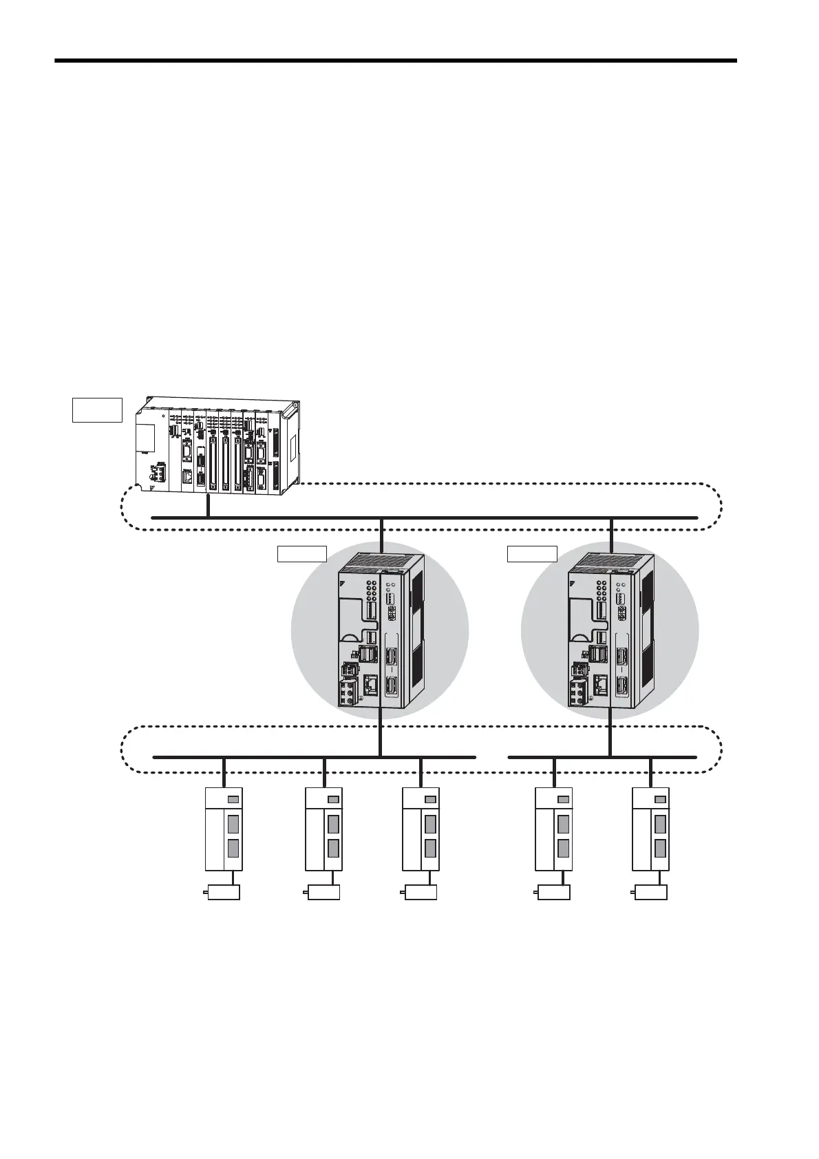
1.3.2 Example of Distributed Synchronizing System
If some MP2300S are connected as slaves and other MP2000-series Machine Controllers are connected via MECHA-
TROLINK-II, slaves can operate synchronously.
Distribution of the load realizes the high-speed synchronization of multiple axes.
MP2300S
SVB-01
Module
Τ
MECHATROLINK-
Τ
MECHATROLINK-
Master
Slave
Synchronization
Synchronization
MP
/
'
VJGTPGV
.+0-
0
0
23
S
&%
&%
8
4.;
176
0V
;#5-#9#
6'56
4&;
#./
/6:
64:
470
'44
$#6
+2
59
59
10
10
%0()
+06
572
/10
5612
$#66'4;
M-I/II
'
'
6'56
+06
01
01
+
MP2300S
SVB-01
Module
Slave
MP
/
'
VJGTPGV
.+0-
0
0
23
S
&%
&%
8
4.;
176
0V
;#5-#9#
6'56
4&;
#./
/6:
64:
470
'44
$#6
+2
59
59
10
10
%0()
+06
572
/10
5612
$#66'4;
M-I/II
'
'
6'56
+06
01
01
+
MP2200
MBU-01
POWER
CPU-01
SVB-01
218IF-01
LIO-02
LIO-01
LIO-01
217IF-01
EXIOIF
260IF-01
YAS KAW A
MP2100,
MP2200,
MP2300,
MP2300S,
MP2310,
MP2400,
MP2500
SVB-01
TX
ERRRUN
SPD
SIZE
M/S
ON
OFF
10
1
M-I/II
CN1
CN2
SVB-01
TX
ERRRUN
SPD
SIZE
M/S
ON
OFF
10
1
M-I/II
CN1
CN2