Page 9 - 3
Motor & Resolver Circuitry
Electrical
Troubleshooting Guide
IRB6400 M94A
9.9. Motor & Resolver CircuitryMotor & Resolver Circuitry
9.1 Overview
This chapter will explain:
- the major components of the Servo system.
- how each component works.
- how the various components interact.
- how to troubleshoot each component.
- what to do when a component is replaced.
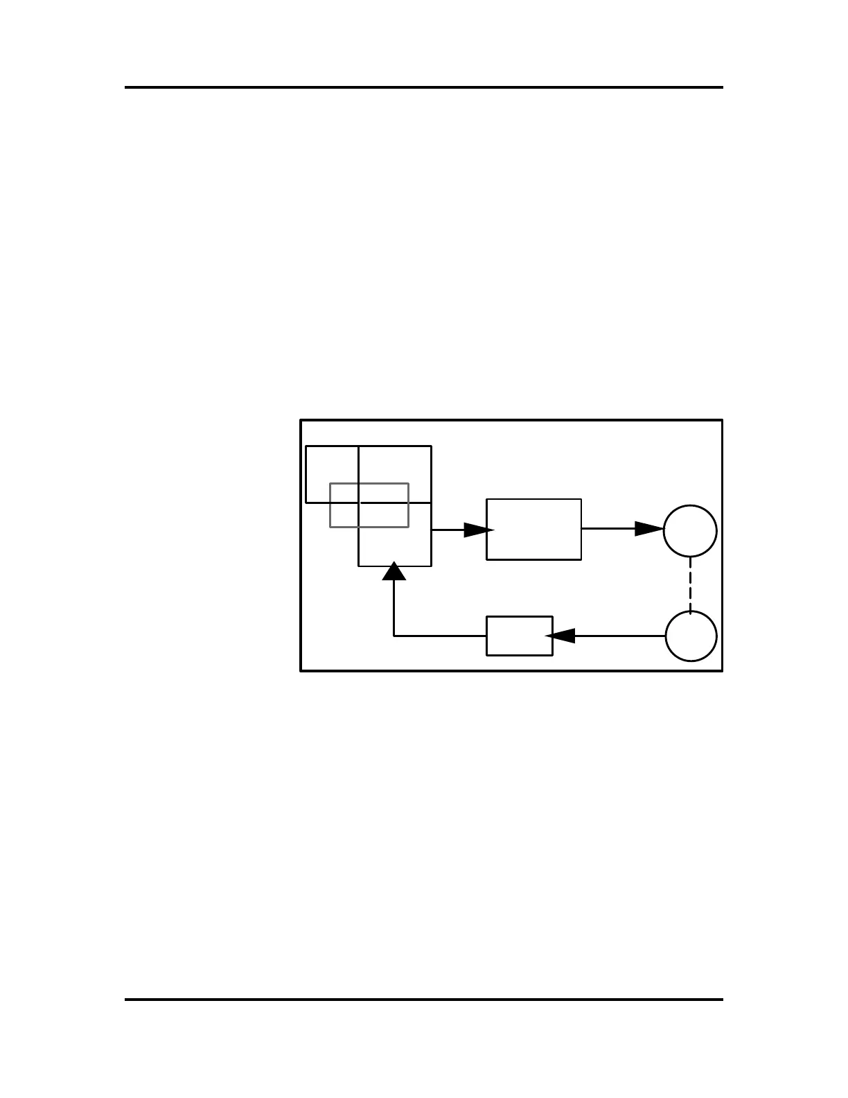
The servo system is a complex system comprised of
computer boards, software, and resolvers along with a
PWM drive system connected to motors. The diagram
below shows these components.
This type of servo system is known as a closed loop
system because a movement command goes out the
robot computer board to the drive system then to the
motors. Connected to each motor is a resolver which is
used for position feedback. These signals go through
the serial measurement board which converts the analog
resolver signals to a digital serial communication which
is sent back to the robot computer. If any component in
this loop is disconnected or fails, the system will generate
a fault.
Diagram 9-1 Closed Loop System
BOAR DS
MAI N
C OMPUTER
D SQC 316
RO BOT
CO MPUTER
DSQC 326
SY STEM
SOFTWA RE
MEMORY
B OARD
D SQC 317
PWM DRIVE
SYSTEM
MOTORS
RESOLVER
SERIAL
MEASUREMENT
BOARD
Artisan Technology Group - Quality Instrumentation ... Guaranteed | (888) 88-SOURCE | www.artisantg.com