en05000114.vsd
TRSP
t
tEF
I0CHECK
AND
BLKI02
t
10 ms
AND
BLKI01
BLOCK
INHIBIT
ZOUTL3
ZOUTL2
ZOUTL1
DET1of3 - int.
REL1PH
BLK1PH
AND
DET2of3 - int.
REL2PH
BLK2PH
AND
EXTERNAL
AND
START
ZOUT
ZINL1
ZINL2
ZINL3
ZIN
AND
t
tR1
t
tR2
OR
AND
AND
OR
OR
OR
OR
OR
t
tH
-loop
-loop
IEC05000114 V1 EN-US
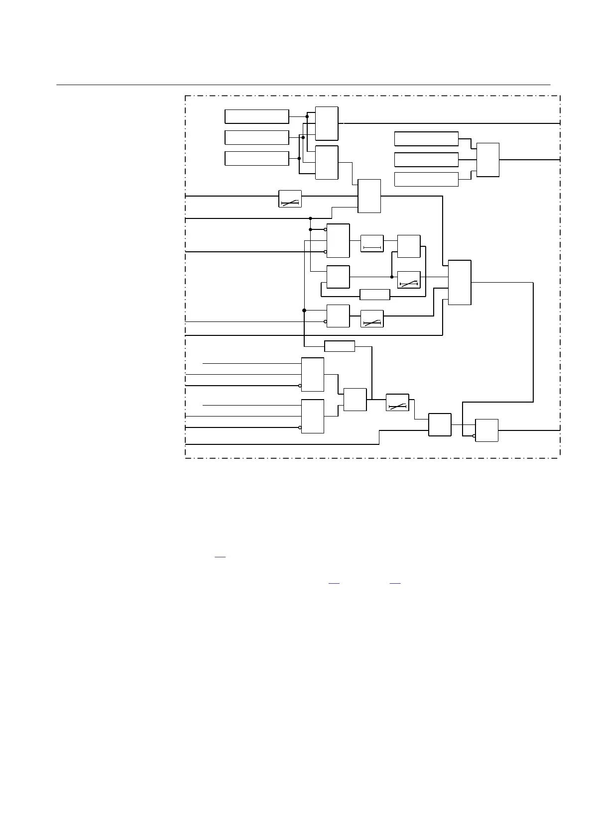
Figure 69: Simplified block diagram for ZMRPSB function
7.2.6.5 Operating and inhibit conditions
M13877-38 v4
Figure
69 presents a simplified logic diagram for the Power swing detection
function ZMRPSB. The internal signals DET1of3 and DET2of3 relate to the
detailed logic diagrams in figure
67 and figure 68 respectively.
Selection of the operating mode is possible by the proper configuration of the
functional input signals REL1PH, BLK1PH, REL2PH, and BLK2PH.
The load encroachment characteristic can be switched off by setting the parameter
OperationLdCh = Off, but notice that the DFw and DRv will still be calculated from
RLdOutFw and RLdOutRv. The characteristic will in this case be only
quadrilateral.
There are four different ways to form the internal INHIBIT signal:
1MRK 505 394-UEN A Section 7
Impedance protection
Line differential protection RED650 2.2 IEC 153
Technical manual