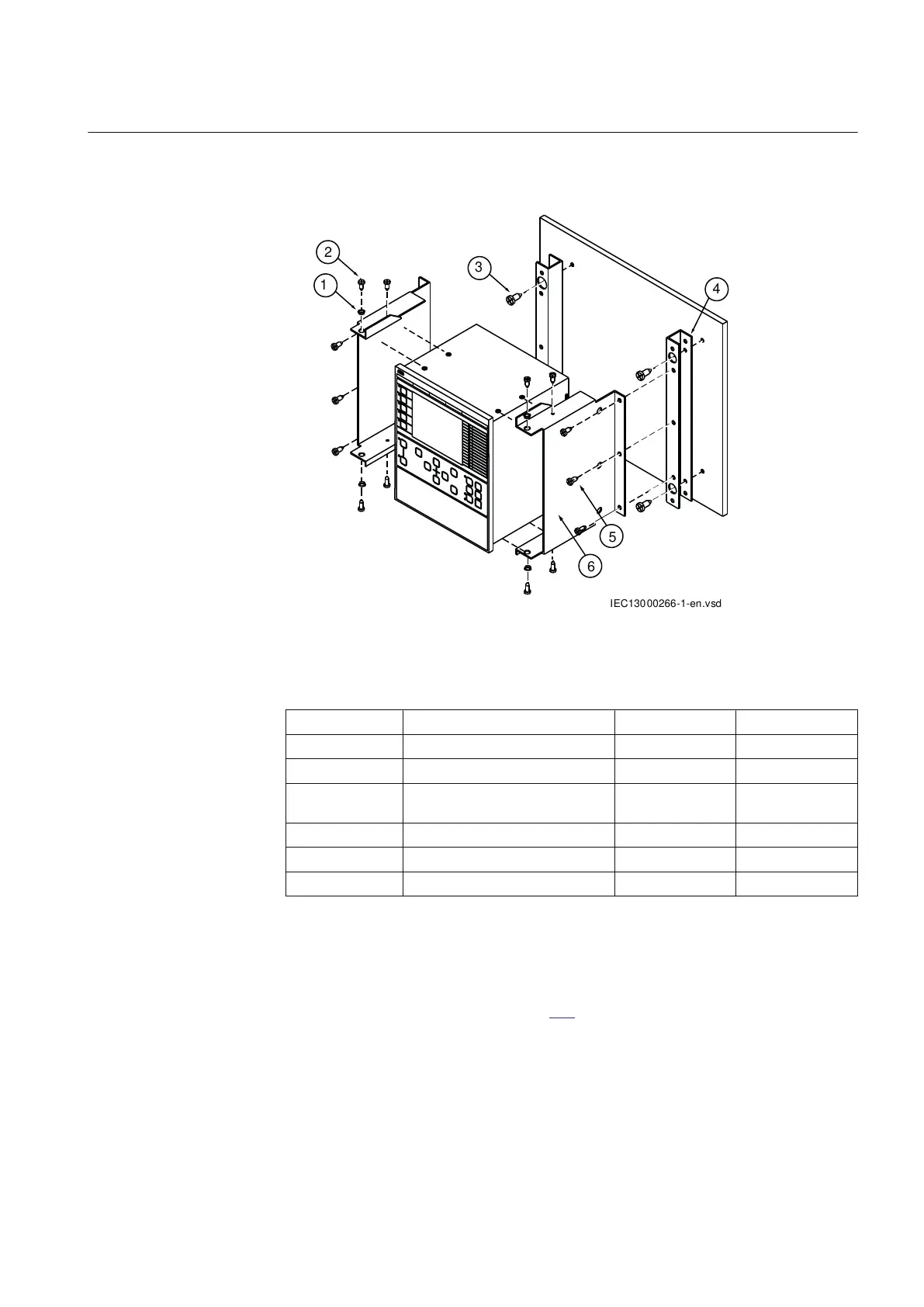
22.4.3.2 Mounting procedure for wall mounting
M11949-2 v2
IEC13000266-1-en.vsd
1
2
3
4
5
6
IEC13000266 V1 EN-US
Figure 401: Wall mounting details.
PosNo
Description Quantity Type
1 Bushing 4 -
2 Screw 8 M4x10
3 Screw 4 M6x12 or
corresponding
4 Mounting bar 2 -
5 Screw 6 M5x8
6 Side plate 2 -
22.4.3.3 How to reach the rear side of the IED
M11941-2 v5
The IED can be equipped with a rear protection cover recommended to be used
with this type of mounting. See figure 402.
To reach the rear side of the IED, a free space of 80 mm is required on the
unhinged side.
1MRK 505 394-UEN A Section 22
IED hardware
Line differential protection RED650 2.2 IEC 855
Technical manual