14.7.1.2 Signals
PID-3437-INPUTSIGNALS v7
Table 273: AND Input signals
Name
Type Default Description
INPUT1 BOOLEAN 1 Input signal 1
INPUT2 BOOLEAN 1 Input signal 2
INPUT3 BOOLEAN 1 Input signal 3
INPUT4 BOOLEAN 1 Input signal 4
PID-3437-OUTPUTSIGNALS v7
Table 274: AND Output signals
Name Type Description
OUT BOOLEAN Output signal
NOUT BOOLEAN Inverted output signal
14.7.1.3 Technical data
GUID-D1179280-1D99-4A66-91AC-B7343DBA9F23 v2
Table 275: Number of AND instances
Logic block
Quantity with cycle time
3 ms 8 ms 100 ms
AND 60 60 160
14.7.2 Controllable gate function block GATE
IP11021-1 v2
M11489-3 v2
The Controllable gate function block (GATE) is used for controlling if a signal
should be able to pass from the input to the output or not depending on a setting.
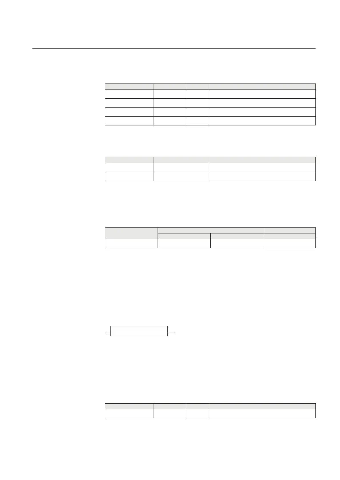
14.7.2.1 Function block
M11490-3 v2
IEC04000410-2-en.vsd
GATE
INPUT OUT
IEC04000410 V2 EN-US
Figure 231: GATE function block
14.7.2.2 Signals
PID-3801-INPUTSIGNALS v6
Table 276: GATE Input signals
Name
Type Default Description
INPUT BOOLEAN 0 Input to gate
1MRK 505 394-UEN A Section 14
Logic
Line differential protection RED650 2.2 IEC 461
Technical manual