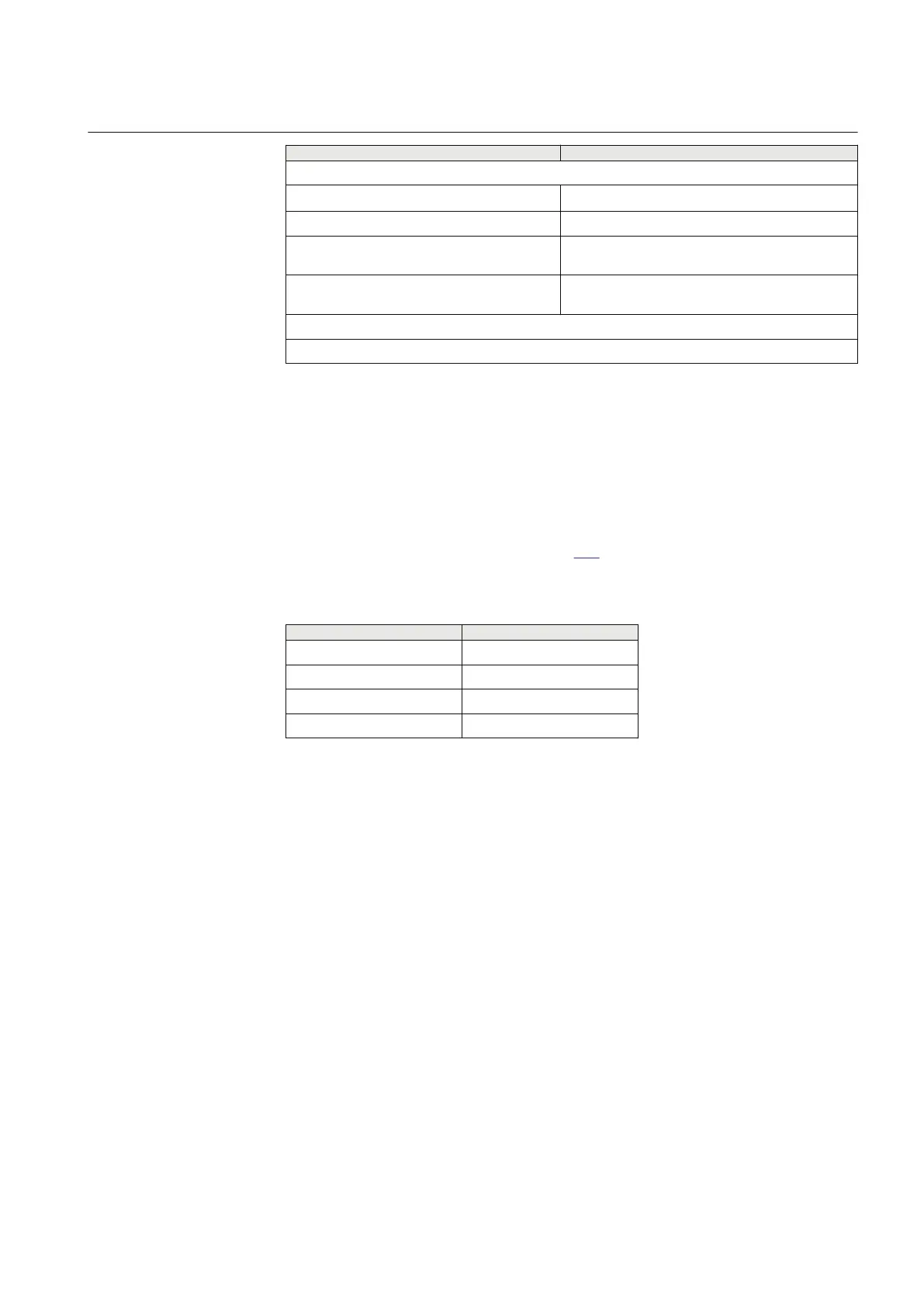
Description Value
Voltage inputs **)
Rated voltage U
r
110 or 220 V
Operating range 0 - 340 V
Thermal withstand 450 V for 10 s
420 V continuously
Burden < 20 mVA at 110 V
< 80 mVA at 220 V
**) all values for individual voltage inputs
Note! All current and voltage data are specified as RMS values at rated frequency
22.2.6 Analog digital conversion module (ADM)
IP14285-1 v2
22.2.6.1 Introduction
M13664-3 v5
The Analog digital conversion module (ADM) has 12 analog inputs, two PC-MIP
slots and one PMC slot. PC-MIP slots are used for PC-MIP cards, and PMC slot is
used for PMC cards as described in Table
619. The SLM card should always be
mounted on the first ADM module.
Table 619: PC-MIP cards and PMC cards
PC-MIP cards
PMC cards
SR-LDCM SLM
MR-LDCM
IRIG-B
RS485
22.2.6.2 Design
M13666-3 v2
The Analog digital conversion module input signals are voltage and current from
the transformer module. Shunts are used to adapt the current signals to the
electronic voltage level. To gain dynamic range for the current inputs, two shunts
with separate A\D channels are used for each input current. In this way a 20 bit
dynamic range is obtained with a 16 bit A\D converter.
Input signals are sampled with a sampling freqency of 5 kHz at 50 Hz system
frequency and 6 kHz at 60 Hz system frequency.
The A\D converted signals goes through a filter with a cut off frequency of 500 Hz
and are reported to the numerical module (NUM) with 1 kHz at 50 Hz system
frequency and 1,2 kHz at 60 Hz system frequency.
1MRK 505 394-UEN A Section 22
IED hardware
Line differential protection RED650 2.2 IEC 817
Technical manual