22.2.3.2 Design
IP14278-1 v1
M6377-3 v2
There are two types of the power supply module. They are designed for different
DC input voltage ranges see table 617. The power supply module contains a built-
in, self-regulated DC/DC converter that provides full isolation between the
terminal and the external battery system.
The DC input is protected against inverse polarity within the rated DC voltage
range.
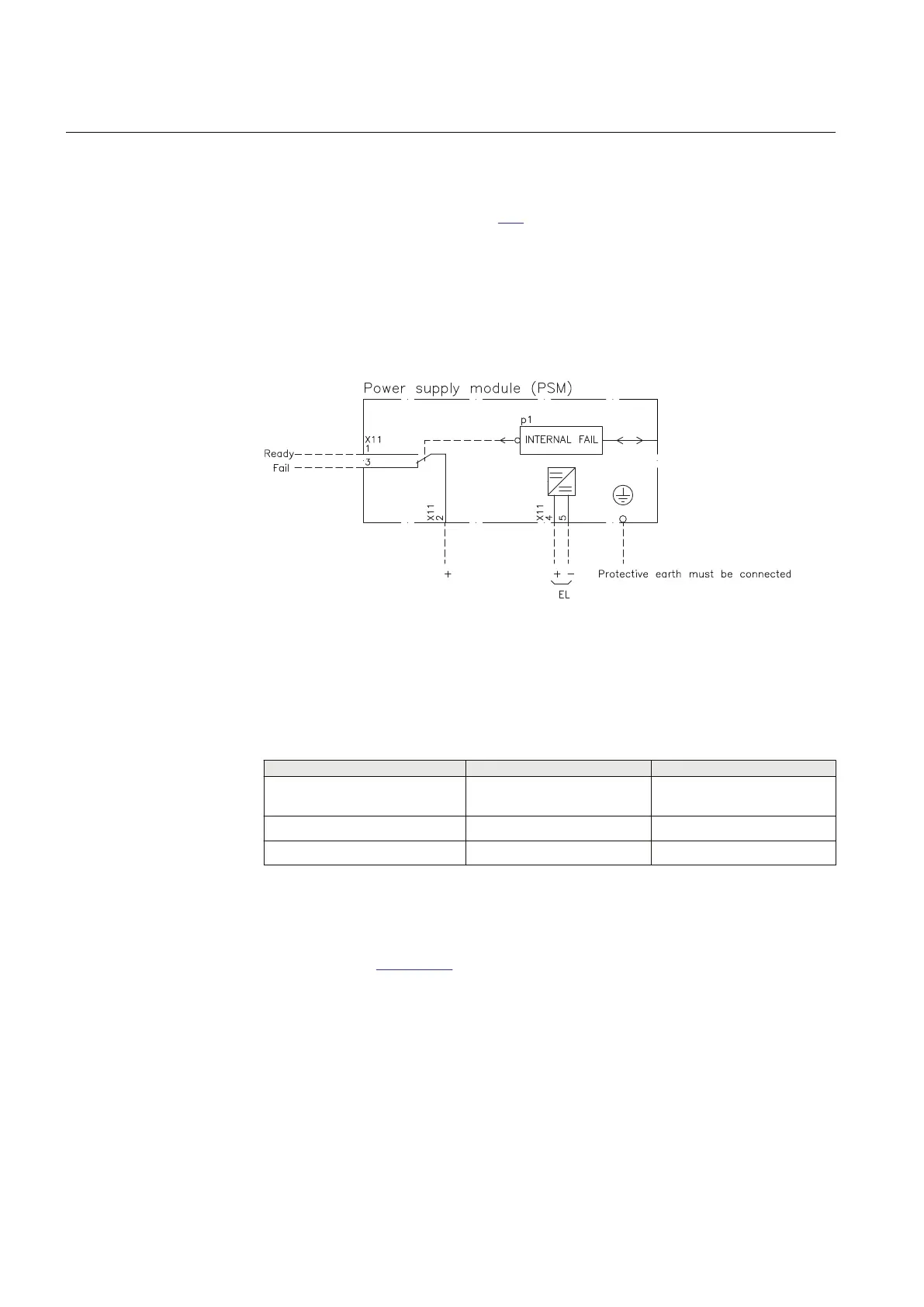
Connection diagram
M6377-8 v3
IEC08000476 V2 EN-US
Figure 374: PSM Connection diagram.
22.2.3.3 Technical data
SEMOD52801-1 v1
M12286-1 v6
Table 617: PSM - Power supply module
Quantity
Rated value Nominal range
Auxiliary DC voltage, EL (input) EL = (24-60) V
EL = (100-250) V
EL ±20%
EL ±20%
Power consumption 32 W typically -
Auxiliary DC power in-rush < 10 A during 0.1 s -
22.2.4 Local human-machine interface (Local HMI)
SEMOD56218-5 v4
Refer to section Local HMI for information.
22.2.5 Transformer input module (TRM)
IP15581-1 v1
Section 22 1MRK 505 394-UEN A
IED hardware
814 Line differential protection RED650 2.2 IEC
Technical manual