22.2.11.2 Design
SEMOD158668-1 v1
SEMOD158670-4 v3
RS485 is a PC-MIP card, and it is factory mounted as a mezzanine card on the
Analog digital conversion module (ADM).
RS485 connector pinouts
SEMOD158670-10 v1
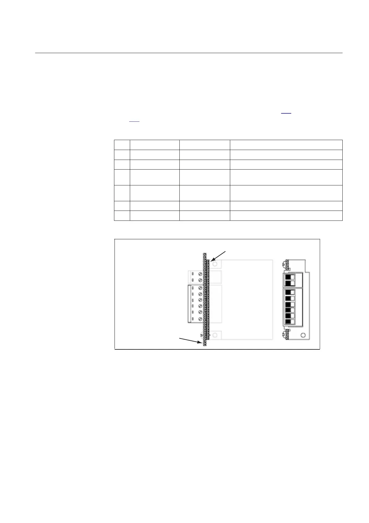
The arrangement for the pins in the RS485 connector (figure 386) are presented in
table 640:
Table 640: The arrangement for the pins
Pin Name 2-wire Name 4-wire Description
1 RS485+ TX+ Receive/transmit high or transmit high
2 RS485– TX– Receive/transmit
3 Term T-Term Termination resistor for transmitter (and receiver
in 2–wir case) (connect to TX+)
4 N.A. R-Term Termination resistor for receiver (connect to RX
+)
5 N.A. RX– Receive low
6 N.A. RX+ Receive high
Screw
terminal
X3
1
2
1
2
3
4
5
6
Screw
terminal
X1
Backplane
Angle
bracket
RS485
PWB
IEC06000517 V1 EN-US
Figure 386: RS485 connector
• 2-wire: Connect pin 1 to pin 6 and pin 2 to pin 5
• Termination (2-wire): Connect pin 1 to pin 3
• Termination (4-wire): Connect pin 1 to pin 3 and pin 4 to pin 6
1MRK 505 394-UEN A Section 22
IED hardware
Line differential protection RED650 2.2 IEC 841
Technical manual