15.10.3.1 Design
GUID-B643C994-D0BA-4BE9-BACB-ADEA0197CAE4 v1
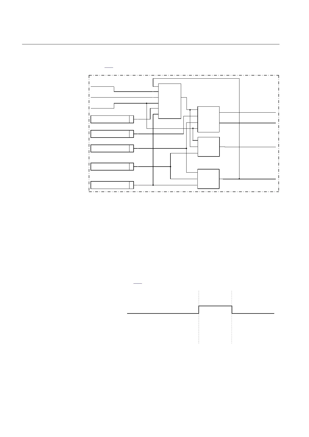
Figure
295 illustrates the general logic diagram of the function.
BLOCK
CountType
INPUT
RESET
ERROR
OVERFLOW
LIMIT1 … 4
CounterLimit1...4
MaxValue
OnMaxValue
InitialValue
VALUE
Operation
Counter
Overflow
Detection
Limit
Check
Error
Detection
IEC12000625_1_en.vsd
IEC12000625 V1 EN-US
Figure 295: Logic diagram
The counter can be initialized to count from a settable non-zero value after reset of
the function. The function has also a maximum counted value check. The three
possibilities after reaching the maximum counted value are:
• Stops counting and activates a steady overflow indication for the next count
• Rolls over to zero and activates a steady overflow indication for the next count
• Rolls over to zero and activates a pulsed overflow indication for the next count
The pulsed overflow output lasts up to the first count after rolling over to zero, as
illustrated in figure
296.
IEC12000626_1_en.vsd
Max value +3
1 2
...
...
...
...
Overflow indication
Actual value
Counted value
IEC12000626 V1 EN-US
Figure 296: Overflow indication when OnMaxValue is set to rollover pulsed
The Error output is activated as an indicator of setting the counter limits and/or
initial value setting(s) greater than the maximum value. The counter stops counting
Section 15 1MRK 505 394-UEN A
Monitoring
600 Line differential protection RED650 2.2 IEC
Technical manual