START
ST1L1
ST1L2
ST1L3
TR1L1
TR1L2
TR1L3
ST1
TR1
START
ST2L1
ST2L2
ST2L3
TR2L1
TR2L2
TR2L3
ST2
TR2
TRIP
Comparator
UL1 < U1<
Comparator
UL2 < U1<
Comparator
UL3 < U1<
MinVoltSelector
Comparator
UL1 < U2<
Comparator
UL2 < U2<
UL3 < U2<
MinVoltSelector
Start t1
&
Trip
Output
Logic
Step 1
Start t2
&
Trip
Output
Logic
Step 2
Phase 3
Phase 2
Phase 1
Phase 3
Phase 2
Phase 1
Time integrator
tIReset2
ResetTypeCrv2
Voltage Phase
Selector
OpMode2
1 out of 3
2 out of 3
3 out of 3
Time integrator
tIReset1
ResetTypeCrv1
Voltage Phase
Selector
OpMode1
1 out of 3
2 out of 3
3 out of 3
UL1
UL2
UL3
TRIP
TRIP
OR
OR
OR
OR
OR
OR
START
IntBlkStVal1
t1Reset
IntBlkStVal2
t2Reset
IEC05000834-2-en.vsd
Comparator
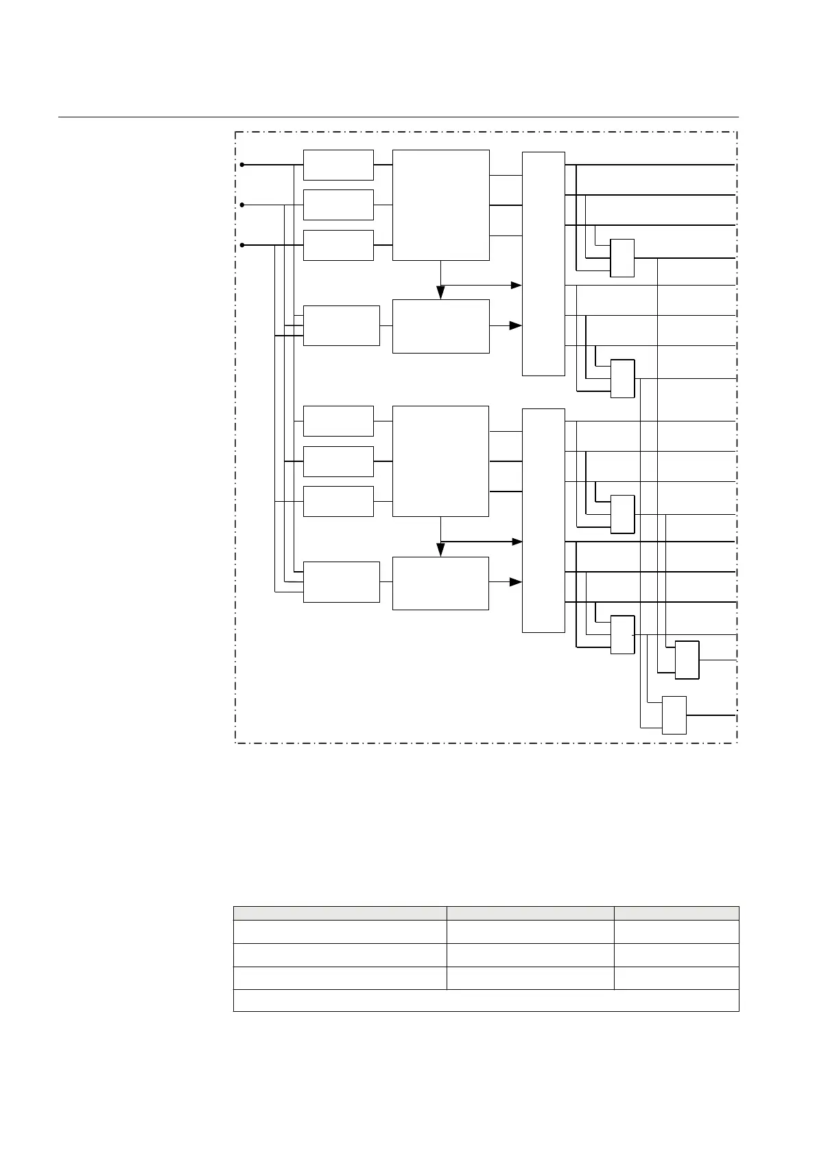
IEC05000834 V2 EN-US
Figure 110: Schematic design of Two step undervoltage protection UV2PTUV
9.1.8 Technical data
IP13001-1 v1
M13290-1 v15
Table 121: UV2PTUV technical data
Function
Range or value Accuracy
Operate voltage, low and high step (1.0–100.0)% of
UBase
±0.5% of U
r
Absolute hysteresis (0.0–50.0)% of
UBase
±0.5% of U
r
Internal blocking level, step 1 and step 2 (1–50)% of
UBase
±0.5% of U
r
Table continues on next page
Section 9 1MRK 505 394-UEN A
Voltage protection
240 Line differential protection RED650 2.2 IEC
Technical manual