DI<
UL1
DU>
a
b
a>b
t
20 ms
t
1.5 cycle
AND
DUDI detection Phase 1
UPh>
DUDI detection Phase 2
Same logic as for phase 1
IL1
DUDI detection Phase 3
Same logic as for phase 1
UL3
a
b
a<b
UL1
IL1
a
b
a>b
IPh>
AND
AND
CBCLOSED
OR
OR
AND
a
b
a<b
UL2
IL2
a
b
a>b
AND
AND
OR
OR
AND
a
b
a<b
UL3
IL3
a
b
a>b
AND
AND
OR
OR
AND
AND
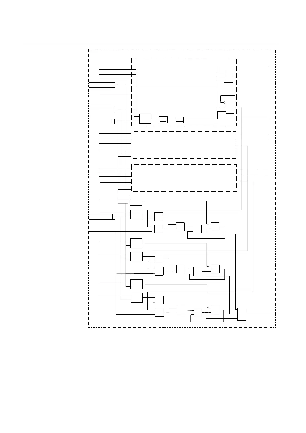
FuseFailDetDUDI
DUDI Detection
DeltaIL1
DeltaUL1
DeltaIL2
DeltaUL2
DeltaIL3
DeltaUL3
IEC12000166-3-en.vsd
IL1
DI detection based on sample analysis
DU detection based on sample analysis
UL2
IL2
IL3
IL3
IL2
IL1
IL2
IL3
OR
IEC12000166 V3 EN-US
Figure 138: Simplified logic diagram for the DU/DI detection part
Section 11 1MRK 505 394-UEN A
Secondary system supervision
294 Line differential protection RED650 2.2 IEC
Technical manual