9.2.10.2
E1402: sensor configuration failure
If this error is displayed during a panoramic or 3D exam it is related to a
communication error between the flat panel and the PC software or a 3D Power
Sensor board A10 problem.
If it is displayed during a ceph exam it is related to a communication problem
between the ceph sensor and the PC or to a problem of the boards A11, A13 and
A14
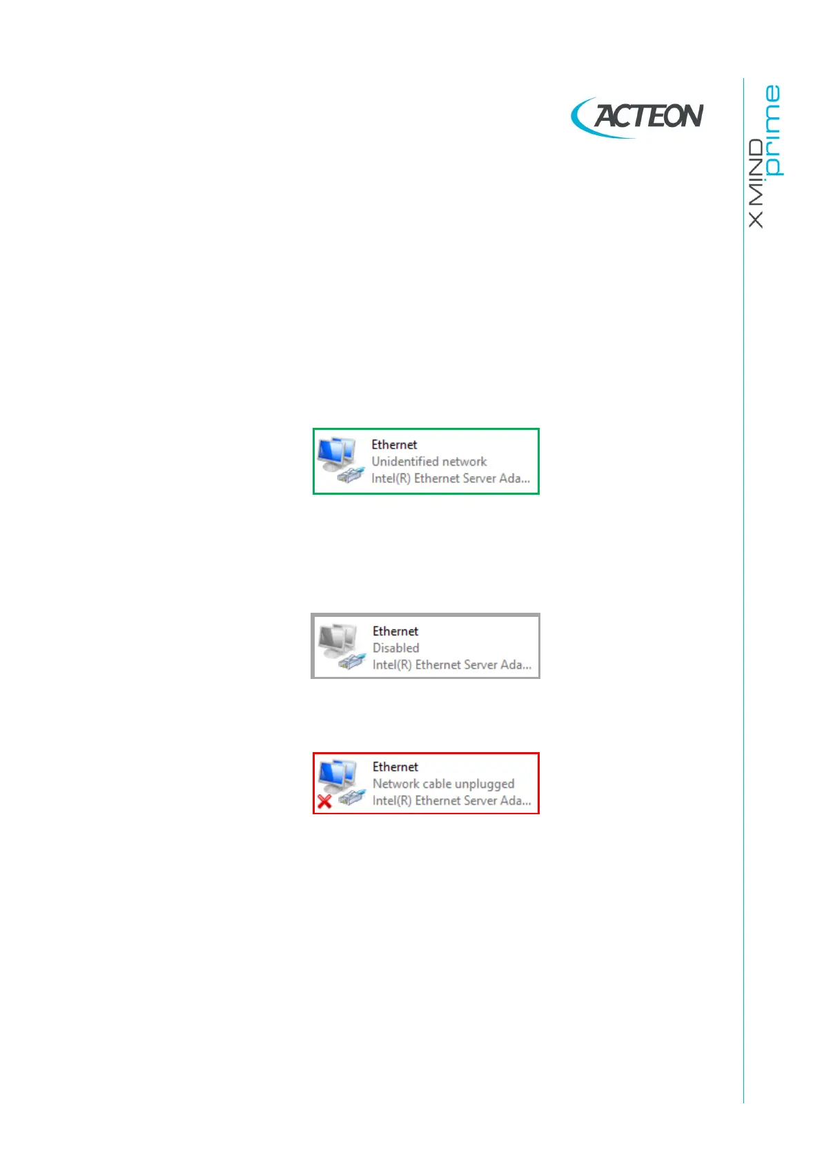
Perform the exam in which the error was displayed in a test mode (without X-ray)
and verify, during the movements the status of the Ethernet connection (Control
Panel
→
Network and Internet
→
Network Connections).
1.
IF the Ethernet connection is steady ACTIVE:
a.
Perform points 1, 2, 3, 4 and 7a of Error E1401 (see paragraph 9.2.10.1).
b.
Activate the sensor logs (see paragraph 11.2.1.4) and perform an
acquisition in order to reproduce the error.
2.
IF the Ethernet connection is DISABLED:
Right click on Network board icon and click on “Enable”.
3.
IF the Ethernet connection is NOT steady ACTIVE:
a.
Check the 3D sensor Ethernet connections (cables, junctions, PC network
board): replace the faulty components (see point 1 of Error E1401 –
paragraph 9.2.10.1).
b.
If the problem occurs during a panoramic or a 3D exam check that the 3D
Power Sensor board A10 is ok by checking that the LED H2 on A10 board is
ON.
•
IF LED H2 is ON: verify the 9V between J99-pin1 and J99-pin6 (3D sensor
side). If NOT OK, replace cable X42-J99.
•
IF LED H2 is OFF: verify if the 3D Power Sensor board A10 fuse is blown.
▪
IF the fuse is blown, verify the integrity of the cable X42-J99, replace
the cable (if faulty) and then the fuse.