Rockwell Automation Publication 2198-UM001I-EN-P - May 2019 195
Interconnect Diagrams Appendix A
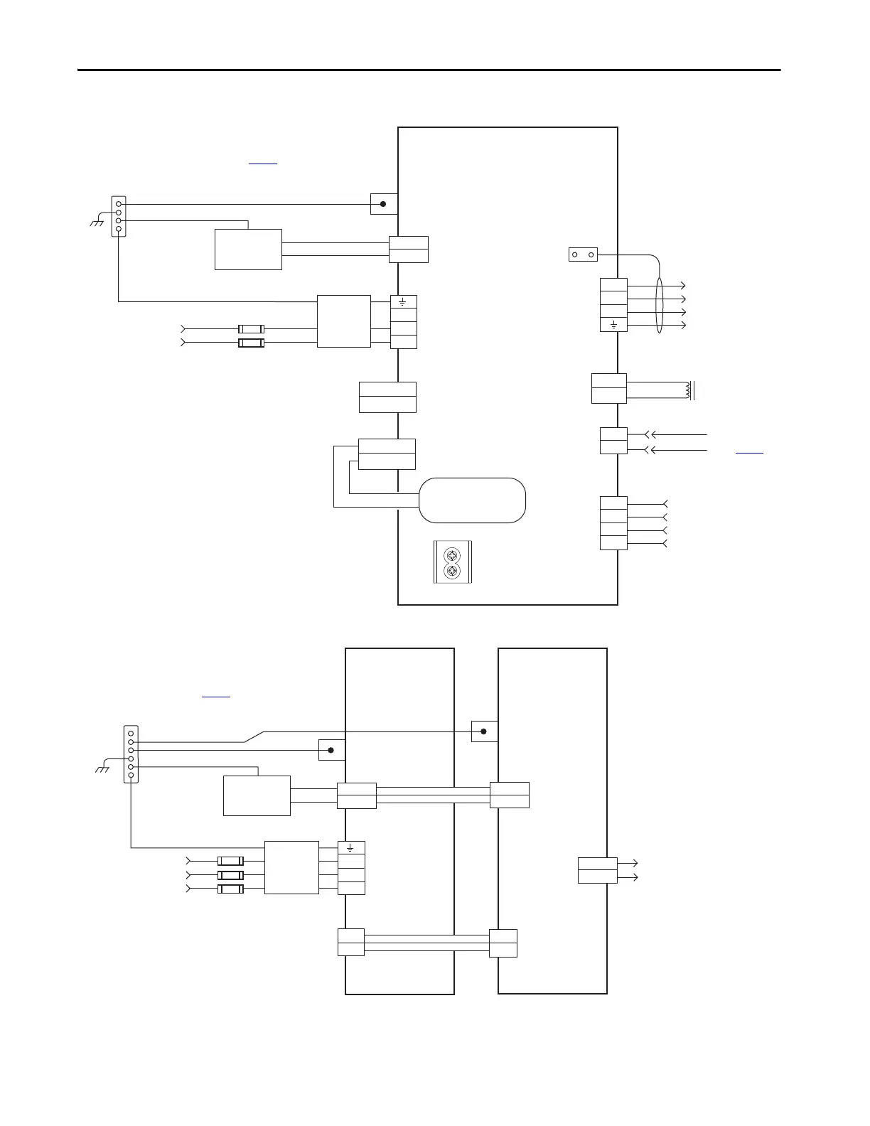
Figure 90 - Kinetix 5500 Drives Power Wiring (single-phase operation)
Figure 91 - Kinetix 5500 Capacitor Module
DATA +/EPWR+
DATA -/EPWR-
L3
L2
L1
2
1
MBRK -
MBRK +
U
V
W
2
1
D+
D-
IN1
COM
IN2
SHLD
1
2
4
3
2
1
4
3
2
1
1
2
3
4
MBRK -
MBRK +
DC+
SH
24V_COM
+24V
DC+
DC-
195…264V AC rms
Single-phase Input
Notes 1, 2
Bonded Cabinet Ground Bus *
Control Power
(CP) Connector
Mains AC Input
(IPD) Connector
* Indicates User Supplied Component
2198-H003-ERSx, 2198-H008-ERSx, or
2198-H015-ERSx
Kinetix 5500 Drives
Chassis
Note 4
Ground Screws
Note 9
Customer Supplied
+24V DC
Power Supply *
Motor Brake
(BC) Connector
Three-phase
Motor Power
Connections
Note 11
Motor Power
(MP) Connector
Cable Shield
Clamp
Refer to table on page 193
for note information.
DC Bus
(DC) Connector
(does not apply in
single-phase operation)
Shunt
(RC) Connector
Motor Feedback
(MF) Connector
Digital Input
(IOD) Connector
Motor Brake
Connections
Motor Feedback
Connections
(refer to Figure 97)
Registration and
Home Input
Connections
Circuit Protection *
Note 2
2198-DBxx-F
Three-phase
AC Line Filter
Note 3
Internal Shunt
Note 8
PE Ground
Note 6
Note 5
24V_COM
+24V
RELAY-
RELAY+
2
1
L3
L2
L1
4
3
2
1
24V_COM
+24V
2
1
DC+
DC-
DC+
DC-
Control Power
(CP) Connectors
DC Bus
(DC) Connectors
* Indicates User Supplied Component
2198-CAPMOD-1300
Capacitor Module
Module Status
(MS) Connector
Relay output to Logix 5000™
controller to monitor capacitor
module status.
Bonded Cabinet Ground Bus *
Chassis
Note 4
Customer Supplied
+24V DC
Power Supply *
Refer to table on page 193
for note information.
2198-Hxxx-ERSx
Kinetix 5500 Drive
PE Ground
Note 6
2198-H0x0-ADP-IN
Bus Bar Connectors
PE Ground
Note 6
2198-DBxx-F
Three-phase
AC Line Filter
Note 3
195…264V AC rms or
324…528V AC rms
Three-phase Input
Notes 1, 2
Circuit Protection *
Note 2
2198-H0x0-DP-T
Bus Bar Connectors
Motor, digital input, and
shunt connections not
shown for clarity.

 Loading...


