194 Rockwell Automation Publication 2198-UM001I-EN-P - May 2019
Appendix A Interconnect Diagrams
Power Wiring Examples
You must supply input power components. The single-phase and three-phase
line filters are wired downstream of the circuit protection.
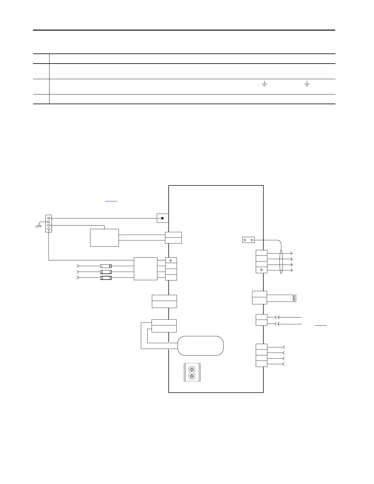
Single-axis Drive Wiring Examples
Figure 89 - Kinetix 5500 Drives Power Wiring (three-phase operation)
13 MPL-Bxx, MPL-A5xx, MPM-Bxx, MPM-A165xx…MPM-A215xx, MPF-Bxx, MPF-A5xx, MPS-Bxxx, MPAR-Bxxx, MPAS-Bxxx, and LDAT-Sxx-xDx encoders use the +9V DC
supply.
14 Brake connector pins are labeled plus (+) and minus (-) or F and G respectively. Power connector pins are labeled U, V, W, and (GND) or A, B, C, and (D)
respectively.
15 LDAT-Series linear thrusters do not have a brake option, so only the 2090-CPWM7DF-xxAAxx or 2090-CPWM7DF-xxAFxx motor power cables apply.
Table 75 - Interconnect Diagram Notes (continued)
Note Information
DATA +/EPWR+
DATA -/EPWR-
L3
L2
L1
24V_COM
+24V
2
1
MBRK -
MBRK +
DC+
DC-
D+
D-
IN1
COM
IN2
SHLD
1
2
4
3
2
1
1
2
3
4
MBRK -
MBRK +
U
V
W
2
1
4
3
2
1
DC+
SH
195…264V AC rms or
324…528V AC rms
Three-phase Input
Notes 1, 2
Bonded Cabinet Ground Bus *
Control Power
(CP) Connector
PE Ground
Note 6
Mains AC Input
(IPD) Connector
Circuit Protection *
Note 2
* Indicates User Supplied Component
2198-Hxxx-ERSx
Kinetix 5500 Drives
Chassis
Note 4
Ground Screws
Note 9
Customer Supplied
+24V DC
Power Supply *
Motor Brake
(BC) Connector
Three-phase
Motor Power
Connections
Note 11
Motor Power
(MP) Connector
Cable Shield
Clamp
Note 5
Refer to table on page 193
for note information.
DC Bus
(DC) Connector
Note 7
Shunt
(RC) Connector
Motor Feedback
(MF) Connector
Digital Input
(IOD) Connector
Motor Brake
Connections
Motor Feedback
Connections
(refer to Figure 97
)
Registration and
Home Input
Connections
2198-DBxx-F
Three-phase
AC Line Filter
Note 3
Internal Shunt
Note 8

 Loading...


