Rockwell Automation Publication 2198-UM001I-EN-P - May 2019 201
Interconnect Diagrams Appendix A
Kinetix 5500 Drive and Linear
Actuator Wiring Examples
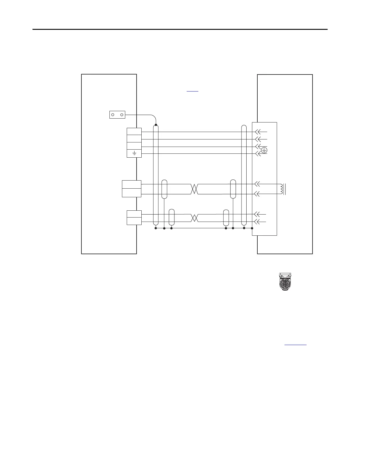
These Kinetix VP linear actuators use single cable technology. The motor
power, brake, and feedback wires are all packaged in a single cable.
Figure 100 - Kinetix 5700 Drives with Kinetix VP Electric Cylinders
2090-CSxM1DF single cables have flying-lead conductors designed
specifically for Kinetix 5500 servo drives. 2090-CSxM1DG cables have flying-
leads that are longer than 2090-CSxM1DF cables to accommodate
Kinetix 5500 or Kinetix 5700 servo drives.
See the cable-shield grounding technique for single cables on page 199
.
U
V
W
1
2
D+
D-
1
2
4
3
2
1
Data+/EPWR+
Data-/EPWR-
Brown
Black
Blue
Green/Yellow
Blue
White/Blue
Black
White
A/U
B/V
C/W
E/1
H/2
F/+
G/–
Shield
MBRK +
MBRK -
Motor
Brake
Motor Brake
(BC) Connector
Motor Power
(MP) Connector
Cable Shield
Clamp
Motor Feedback
(MF) Connector
Three-phase
Motor Power
Motor
Feedback
2198-KITCON-DSL
Connector Kit
VPAR-Bxxxxx-P/Q/W
Electric Cylinders
with High-resolution
Feedback
Power, Brake, and
Feedback Connector
SpeedTec DIN
Single Motor Connector
2198-Hxxx-ERSx
Kinetix 5500 Servo Drives
Note 5
2090-CSBM1DF-xxAAxx
or 2090-CSBM1DF-xxAFxx
or
2090-CSBM1DG-xxAAxx
or 2090-CSBM1DG-xxAFxx
Single Motor Cable
Note 11
Refer to table on page 193
for note information.
Note 14

 Loading...


