Rockwell Automation Publication 2198-UM001I-EN-P - May 2019 63
Connector Data and Feature Descriptions Chapter 4
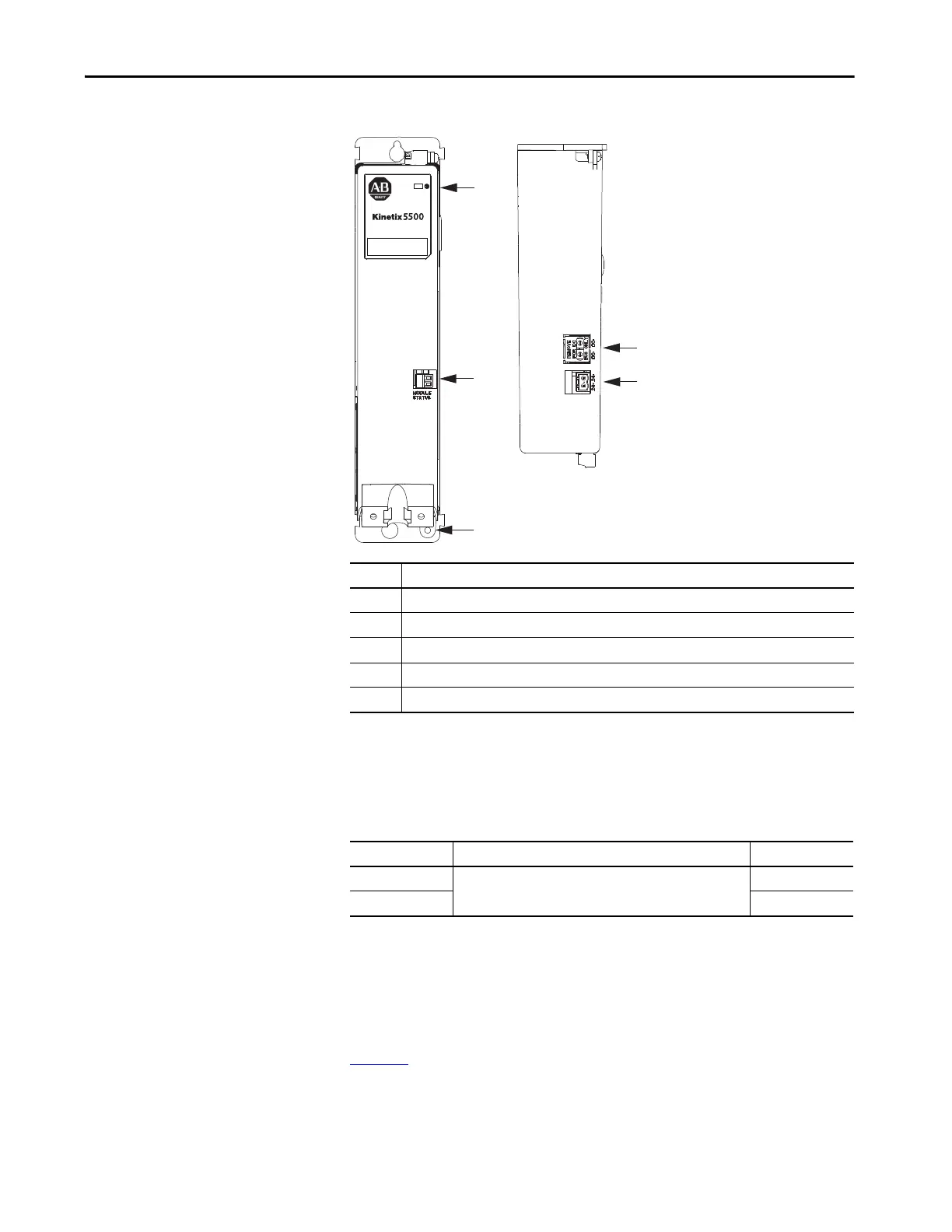
Figure 31 - Capacitor Module Features and Indicators
Module Status Connector Pinout
Safe Torque-off Connector Pinout
For the hardwired safe torque-off (STO) connector pinouts, feature
descriptions, and wiring information, refer to Chapter 9 beginning on
page 169
.
Kinetix 5500 Capacitor Module
Top View
Kinetix 5500 Capacitor Module
Front View
Item Description
1 Ground screw (green)
2 Module status (MS) connector (relay output)
3 Module status indicator
4 DC bus (DC) connector (under cover)
(1)
(2)
5 24V control input power (CP) connector
(2)
(1) The DC-bus connector ships with a protective knock-out cover that can be removed for use in shared-bus configurations.
(2) The shared-bus connector set for the capacitor module, catalog number 2198-KITCON-CAP1300, is included for connection to
the upstream drive. Replacement kits are also available.
MS Pin Description Signal
1
Module status output
MS
2MS

 Loading...


