Rockwell Automation Publication 2198-UM001I-EN-P - May 2019 101
Connect the Kinetix 5500 Drive System Chapter 5
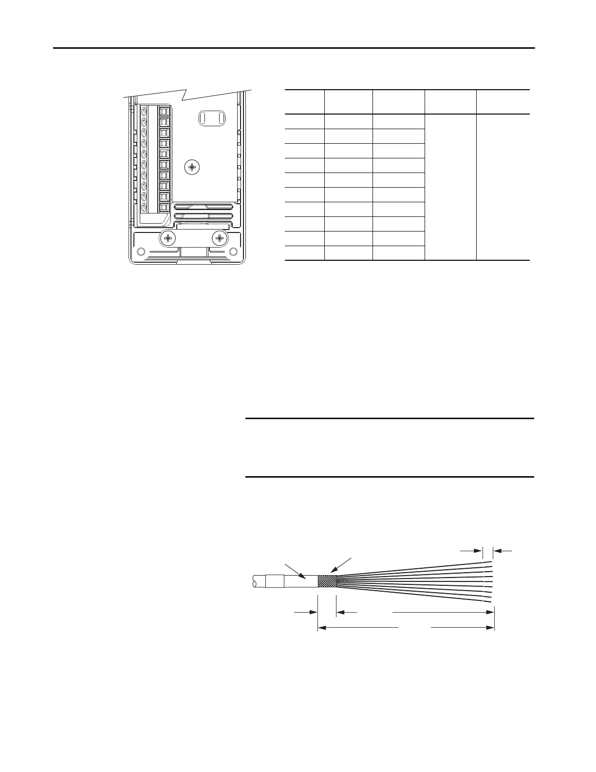
Figure 57 - 2198-H2DCK Converter Kit Pinout
Motor Feedback Cable Preparation
Follow these steps to prepare feedback cables.
1. Remove 115 mm (4.5 in.) of cable jacket and 103 mm (4.0 in.) of cable
shield.
2. Determine the length for each of the 10 wires and trim as necessary.
3. Remove 5.0 mm (0.2 in.) of insulation from the end of each wire.
14
11
10
7
6
5
4
3
2
1
Terminal
Signal
Wire Color
Strip Length
mm (in.)
Torque Value
N•m (lb•in)
1 SIN+ Black
5.0 (0.2)
0.22…0.25
(1.9…2.2)
2 SIN– White/Black
3 COS+ Red
4 COS– White/Red
5DATA+ Green
6 ECOM
(1)
(1) The ECOM and TS- connections are tied together and connect to the cable shield.
White/Gray
7EPWR_9V
(2)
(2) The converter kit generates 5V and 9V from a 12V supply coming from the drive. The 5V supply is
used by 5V encoders in 230V motors. The 9V supply is used by 9V encoders in 460V motors.
Orange
10 DATA– White/Green
11 TS White/Orange
14 EPWR_5V
(2)
Gray
10-pin
Connector
IMPORTANT This length of wire is needed to provide a service loop for the
longest wires terminated at the 10-pin connector. However, most
wires need to be trimmed shorter, depending on the terminal they
are assigned to.
12.0 (0.5)
5.0 (0.2)
115 (4.5)
103 (4.0)
Cable Jacket
Cable Shield
Dimensions are in mm (in.)

 Loading...


