218 Rockwell Automation Publication 2198-UM001I-EN-P - May 2019
Appendix C Size Multi-axis Shared-bus Configurations
Shared AC Configurations
In shared AC configurations, the first (leftmost) drive receives AC input
voltage. The shared-bus connection system extends the AC bus to all
downstream drives:
• All drives are configured in the project file as Standalone drives.
• Drives must be of the same power rating (catalog number).
• Shared AC configurations do not support Bulletin 2198 capacitor
modules.
• The maximum number of drives in Shared AC configurations is
restricted as described in Ta b le 78
.
Table 78 - Shared AC Panel Layout
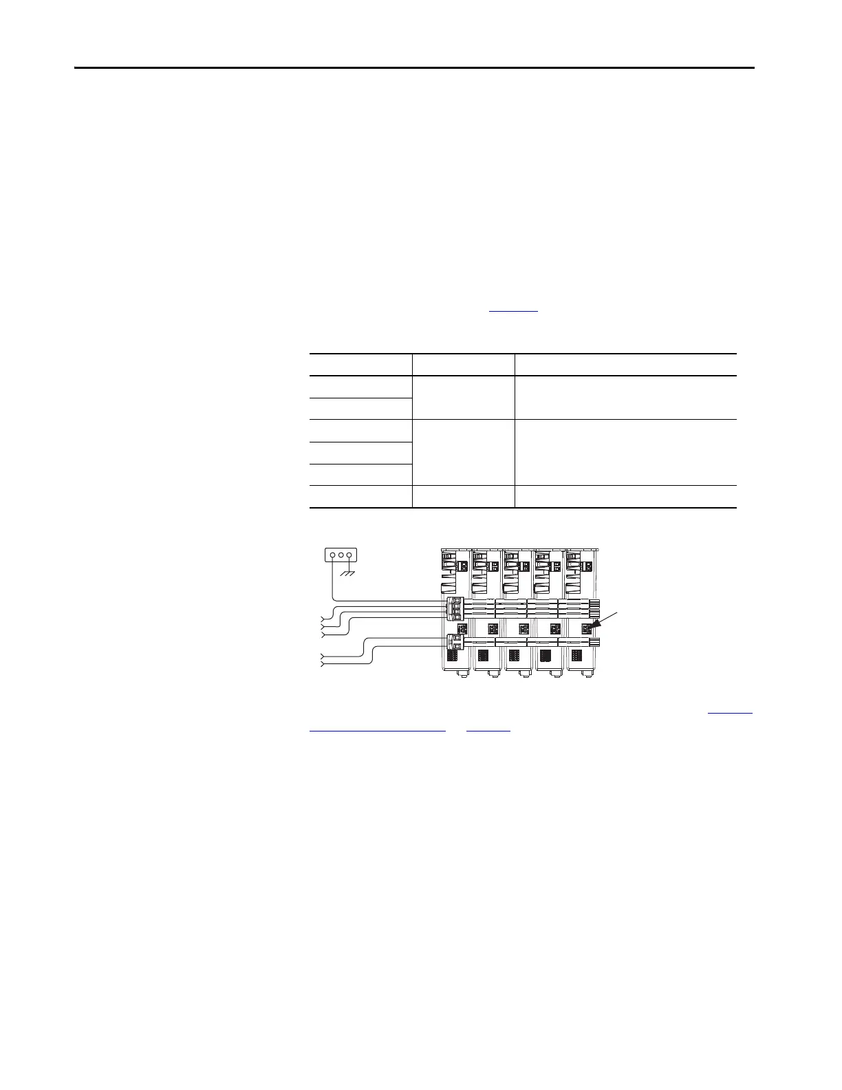
Figure 106 - Typical Shared AC Configuration
For an example shared AC installation with additional details, refer to Typical
Shared AC Installations on page 18.
Shared DC Configurations
In a Shared DC (DC common bus) configuration, the first (leftmost) drive is
the leader drive and is the only drive that receives the AC input voltage. All
drives to the right of the leader drives are follower drives. They receive the DC
bus voltage extended from the leader drive through the shared-bus connection
system:
• For DC common-bus installations, the power rating of the leader drive
must be greater than or equal to the power rating of the follower drives.
• The leader drive is configured in the project file as Shared AC/DC.
• The follower drives are configured in the project file as Shared DC.
• Shared DC configurations support Bulletin 2198 capacitor modules.
Drive Cat. No. Frame Size Number of Drives Configured as Shared AC, max
2198-H003-ERSx
15
2198-H008-ERSx
2198-H015-ERSx
232198-H025-ERSx
2198-H040-ERSx
2198-H070-ERSx 32
Bonded Cabinet
Ground
Three-phase
Input Power
Kinetix 5500 Servo Drives
(top view)
24V Input
Control Power
Do not remove the protective
knock-out DC connector cover.

 Loading...


