148 Rockwell Automation Publication 2198-UM001I-EN-P - May 2019
Chapter 6 Configure and Start the Kinetix 5500 Drive System
Test and Tune the Axes
This procedure assumes that you have configured your Kinetix 5500 drive,
your Logix 5000 controller, and applied power to the system.
For help using the Logix Designer application as it applies to testing and tuning
your axes with ControlLogix EtherNet/IP modules or CompactLogix 5370
controllers, refer to Additional Resources
on page 12.
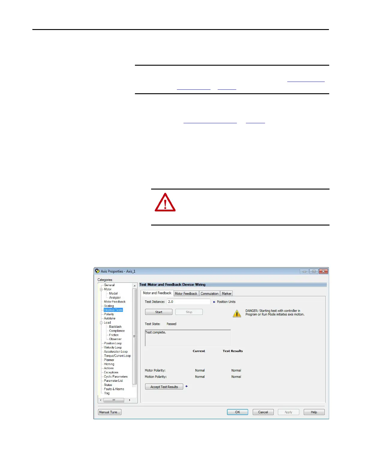
Test the Axes
Follow these steps to test the axes.
1. Verify the load was removed from each axis.
2. In your Motion Group folder, right-click an axis and choose Properties.
The Axis Properties dialog box appears.
3. Click the Hookup Tests category.
4. In the Test Distance field, enter the desired test distance.
The Position Units are defined in the Axis Properties>Scaling tab.
IMPORTANT Before proceeding with testing and tuning your axes, verify that the MOD
and NET status indicators are operating as described in Kinetix 5500 Drive
Status Indicators on page 158.
ATTENTION: To avoid personal injury or damage to equipment, you
must remove the load from each axis as uncontrolled motion can
occur when an axis with an integral motor brake is released during
the test.

 Loading...


