92 Rockwell Automation Publication 2198-UM001I-EN-P - May 2019
Chapter 5 Connect the Kinetix 5500 Drive System
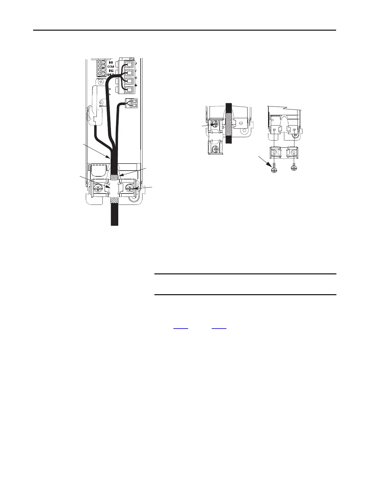
When the drive/motor combination calls for 14 or 10 AWG cable, the
feedback cable routes along with the power and brake wiring.
2. Position the exposed portion of the cable shield directly in line with the
clamp.
3. Tighten each screw a few turns at a time until the maximum torque
value of 2.0 N•m (17.7 lb•in) is achieved.
4. Repeat step 1
through step 3 for each drive in multi-axis configurations.
Wire Other Allen-Bradley
Motors and Actuators
Kinetix 5500 drives are also compatible with many other Allen-Bradley®
motors and actuators, however the 2198-H2DCK Hiperface-to-DSL feedback
converter kit is required for converting the 15-pin Hiperface feedback signals
to 2-pin DSL feedback signals.
Follow these guidelines when 2090-CPxM7DF (power/brake) cables and
2090-CFBM7DF (feedback) cables are used in a new installation or reused in
an existing installation with Kinetix 5500 servo drives. MP-Series™ servo
motors and actuators have separate connectors for 2090-CPxM7DF power/
brake cables and 2090-CFBM7DF feedback cables.
Motor Cable
Shield Clamp
Motor Power
(MP) Connector
Motor Brake
(BC) Connector
Exposed shield braid
under clamp.
Shield Clamp Screws (2)
Feedback cable routed
within the shield braid.
Kinetix 5500 Servo Drives,
Frame 2 or 3, Front View
(frame 2 is shown)
2198-KITCON-DSL
Motor Feedback
Connector Kit
Retention Screw
(loosen, do not remove)
Clamp features apply to all
frame sizes.
Torque clamp screws to
2.0 N•m (17.7 lb•in), max
2090-CSBM1DF-14AAxx
Single Motor Cable
Servo Drive
Shield Clamp
Clamp Screws
2.0 N•m (17.7 lb•in)
Retention
Screw
14 and 10 AWG Cable Installation
IMPORTANT Loosen the retention screw, if needed, until you can start threading
both clamp screws with the cable shield under the clamp.

 Loading...


