Rockwell Automation Publication 2198-UM001I-EN-P - May 2019 79
Connect the Kinetix 5500 Drive System Chapter 5
Remove the Ground Screws
in Select Power
Configurations
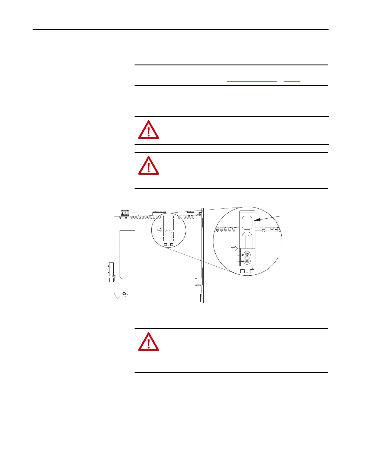
Removing the ground screws involves gaining access, opening the sliding door,
and removing the screws.
Removing the ground screws in multi-axis configurations is best done when
each drive is removed from the panel and placed on its side on a solid surface.
Figure 42 - Remove the Ground Screws
IMPORTANT If you have grounded-wye power distribution, you do not need to remove
the ground screws. Go to Ground the Drive System
on page 80.
ATTENTION: Because the unit no longer maintains line-to-neutral voltage
protection, the risk of equipment damage exists when you remove the
ground screws.
ATTENTION: To avoid personal injury, the ground screws access door must
be kept closed when power is applied. If power was present and then
removed, wait at least 5 minutes for the DC-bus voltage to dissipate and
verify that no DC-bus voltage exists before accessing the ground screws.
Ground screws installed for grounded power configuration
(screws installed is default setting).
• Remove both screws for ungrounded, corner-grounded, and
impedance-grounded power for three-phase operation
• Remove only the AC screw for single-phase operation
Ground Screws
Access Door
Kinetix 5500 Drive
(side view)
Lift door to meet
arrow at left.
AC Screw
DC Screw
ATTENTION: Risk of equipment damage exists. The drive ground
configuration must be accurately determined. Leave the ground screws
installed for grounded power configurations (default). Remove the screws
for ungrounded, corner-grounded, and impedance-grounded power
configurations.

 Loading...


