68 Rockwell Automation Publication 2198-UM001I-EN-P - May 2019
Chapter 4 Connector Data and Feature Descriptions
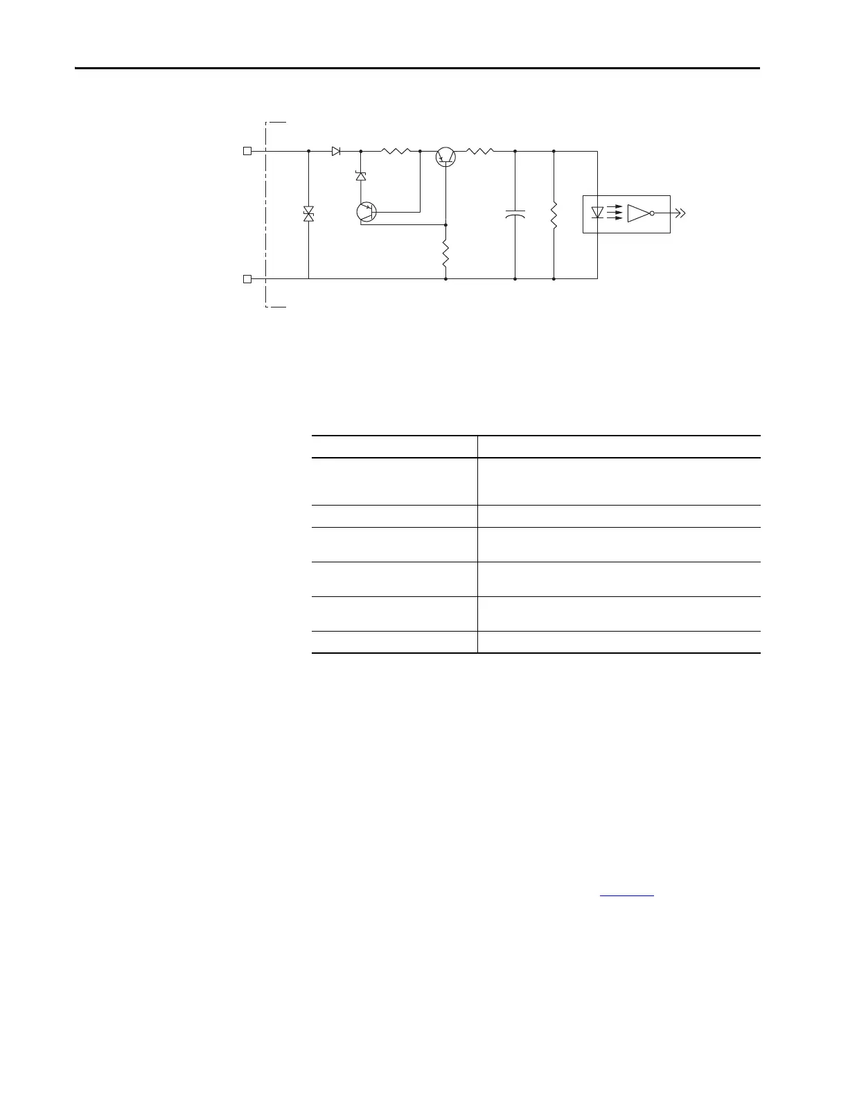
Figure 34 - Digital Input Circuitry
Ethernet Communication Specifications
The PORT1 and PORT2 (RJ45) Ethernet connectors are provided for
communication with the Logix 5000™ controller.
Motor Brake Circuit
The brake option is a spring-set holding brake that releases when voltage is
applied to the brake coil in the motor. The customer-supplied 24V power
supply drives the brake output through a solid-state relay. The solid-state brake
driver circuit provides the following:
• Brake current-overload protection
• Brake over-voltage protection
Two connections (BC-1 and BC-2) are required for the motor brake output.
Connections are rated for 2.0 A @ +24V (refer to Figure 35
).
INPUT
COM
INx
IOD-1 or IOD-3
IOD-2
Attribute Value
Communication
The drive auto-negotiates speed and duplex modes. These modes can
be forced through the Logix Designer application. 100BASE-TX, full
duplex is recommended for maximum performance.
Cyclic update period 1.0 ms, min
Embedded switch features
Three-port, cut-through, time correction on IEEE-1588 packets, limited
filtering, quality of service with four priority levels
Auto MDI/MDIX crossover detection/
correction
Yes
Port-to-port time synchronization
variation
100 ns, max
Cabling CAT5e shielded, 100 m (328 ft) max

 Loading...


