Rockwell Automation Publication 2198-UM001I-EN-P - May 2019 97
Connect the Kinetix 5500 Drive System Chapter 5
Follow these steps to prepare your existing 14 AWG cables, and 12 and
10 AWG (series A) cables.
1. Remove a total of 325 mm (12.8 in.) of cable jacket from your existing
cable.
This exposes additional cable shield.
2. Remove all but 63.5 mm (2.5 in.) of the shield.
3. Cover 12.5 mm (0.5 in.) of the shield ends and an equal length of the
conductors with 25 mm (1.0 in.) of electrical tape or heat shrink.
Do the same on the other side of the cable shield. This keeps the shield
ends from fraying and holds the conductors together.
4. Cut the brake conductors back to 163 mm (6.4 in.) and trim the shield
braid at the base of the jacket.
The shield braid covering the brake conductors is not needed.
5. Remove the specified length of insulation from the end of each wire.
This example applies to existing 2090-CPBM7DF (14 AWG) cables, and 12
and 10 AWG (series A) cables. If you are using a 2090-CSBM1DF/DG single
motor cable, you can remove the shield braid covering the brake conductors.
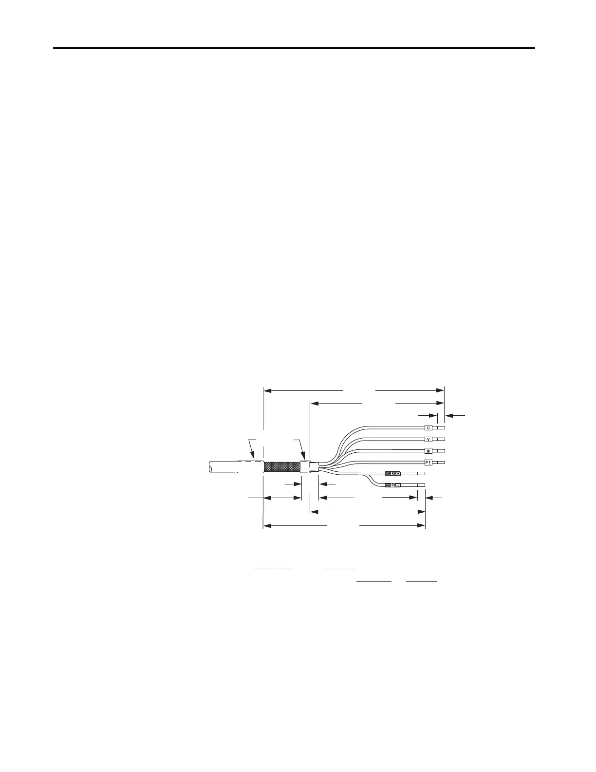
Figure 55 - Power/brake Cable (14, 12, and 10 AWG)
(1) The overall shield braid covering the brake conductors can be removed.
Refer to Figure 56 and on page 99 for a typical installation example. For strip
lengths and torque values, refer to Table 40
on page 89.
7.0 (0.28)
51.0 (2.0)
25.0 (1.0)
221 (8.7)
284 (11.2)
325 (12.8)
262 (10.3)
155 (6.1)
Dimensions are in mm (in.)
Motor Conductors
Brake
Conductors
(1)
Electrical Tape
or Heat Shrink
8.0 (0.31) Frame 1 and 2 drives
10.0 (0.39) Frame 3 drives

 Loading...


