196 Rockwell Automation Publication 6000-TD004D-EN-P - November 2017
Chapter 2 Parameter Descriptions
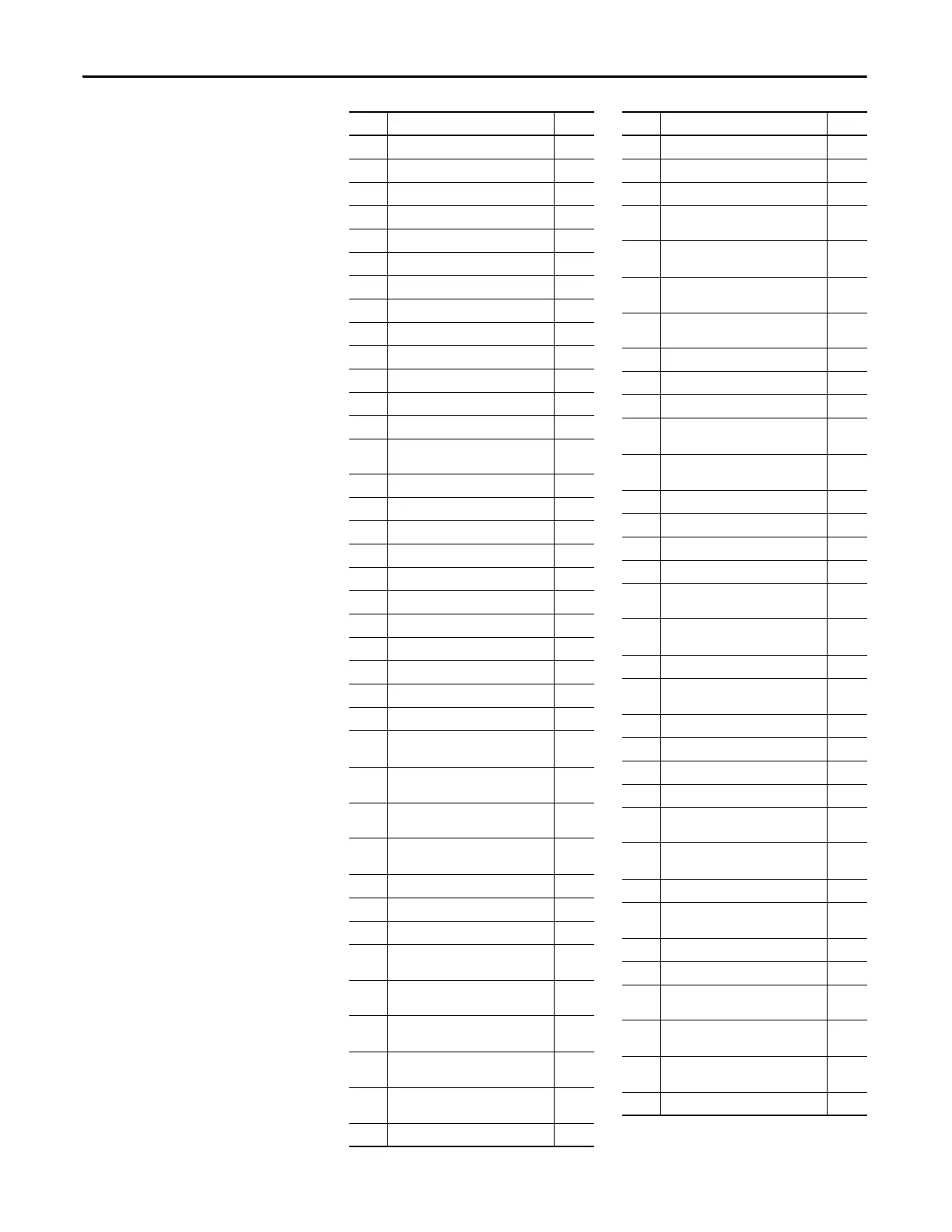
P187 Flying Start Voltage Threshold 114
P195 Line CT Ratio 53
P196 Line CT Burden Resistor 53
P197 Motor HECS Ratio 53
P198 Motor HECS Burden Resistor 53
P199 Motor Rated Current 54
P200 Ia Motor Current Memory Address 73
P201 Motor Ia Scaling Factor 74
P202 Ic Motor Current Memory Address 74
P203 Motor Ic Scaling Factor 74
P204 Motor Uab Voltage Address 74
P205 Motor Uab Voltage Scaling Factor 75
P206 Motor Uac Voltage Scaling Factor 75
P208 Phase Over Current Enable Frequency
Range Upper limit
141
P209 Phase Over Current Filter Time 142
P210 Phase Over Current Threshold 142
P211 Filter Time For Abnormal Output Voltage 142
P212 Filter Time For Output Short-Circuit 142
P213 Output Short-Circuit Fault Threshold 143
P214 Motor Minimum Overload Current 143
P215 Motor Overload Cycle Time 143
P216 MotorOverload Trip Threshold 143
P217 Motor Overload Time 144
P221 Filter Time For Output Over Voltage 144
P222 Output Over Voltage Fault Threshold 144
P223 Output Voltage Deviation Warning
Threshold
144
P224 Output Voltage Deviation Fault
Threshold
145
P226 Output Voltage Abnormality Warning
Cancellation Threshold
145
P227 Ground Fault Detection Scaling
Correction Factor
145
P228 Filter Time For Ground Fault 145
P229 Ground Fault Warning Threshold 146
P230 Ground Fault Trip Threshold 146
P231 Filter Time For Overspeed Fault (Upper
Limit)
146
P232 Filter Time For Overspeed Fault (Lower
Limit)
146
P233 Threshold Of Over-Speed Fault At Lower
Frequency Limit
147
P234 Threshold Of Over-Speed Fault At Upper
Frequency Limit
147
P235 Frequency Deviation Warning
Cancellation Threshold
147
P236 Frequency Deviation Warning Threshold 147
No. Parameter Name Page
P237 Frequency Deviation Warning Delay 148
P238 Motor Stall Fault Threshold 148
P239 Motor Stall Fault Delay 148
P240 Transformer Over Temperature Fault
Delay
148
P241 Transformer Over Temperature Warning
Delay
149
P250 Input Contactor/Circuit Breaker Close
Delay
54
P251 Frequency Command-Low Frequency
Region Boundary
63
P252 Motor In Stopping Condition Threshold 63
P253 Motor Coast Stop Time 63
P254 DC Bus Under Voltage Fault Threshold 150
P256 Ground Fault Warning Cancellation
Threshold
149
P257 Motor Stall Warning Cancellation
Threshold
149
P258 DC Bus Under Voltage Fault Delay 150
P263 Power Loss Restart Enable 102
P264 Power Loss Allowable Time 103
P265 Power Loss Time Max Limit 103
P266 DC Bus Voltage Deviation Fault
Threshold
150
P267 DC Bus Voltage Deviation Fault Filter
Time
150
P268 Flux Control Signal Filter Time 97
P269 System Derating Control Signal Filter
Time
97
P270 Delayed Lockout Time of Stop Operation 64
P271 Flux Delay 66
P272 Flux Control Compensation Gain 97
P273 Flux Control Regulation Control Enable 97
P274 DC Bus Under Voltage Warning
Threshold
150
P275 DC Bus Under Voltage Warning
Hysteresis Band
151
P276 Flux Control-Lag Band Width 98
P277 DC Link Voltage Sag Scaling At Rated
Load
54
P278 Derating Control Enable Threshold 98
P279 Derating Control Output Filter Time 98
P280 Low Voltage Ride Through Recovery
Voltage Boost Coefficient
100
P281 Low Voltage Ride Through Min Time
Interval
100
P282 Low Voltage Ride Through Min
Frequency Limit
100
P283 Low Voltage Ride Through Enable 100
No. Parameter Name Page

 Loading...


