Chapter 3 Measurement Examples
3-2
3.1 Measuring Bit Error Rate
When the DUT input/output signal is electrical:
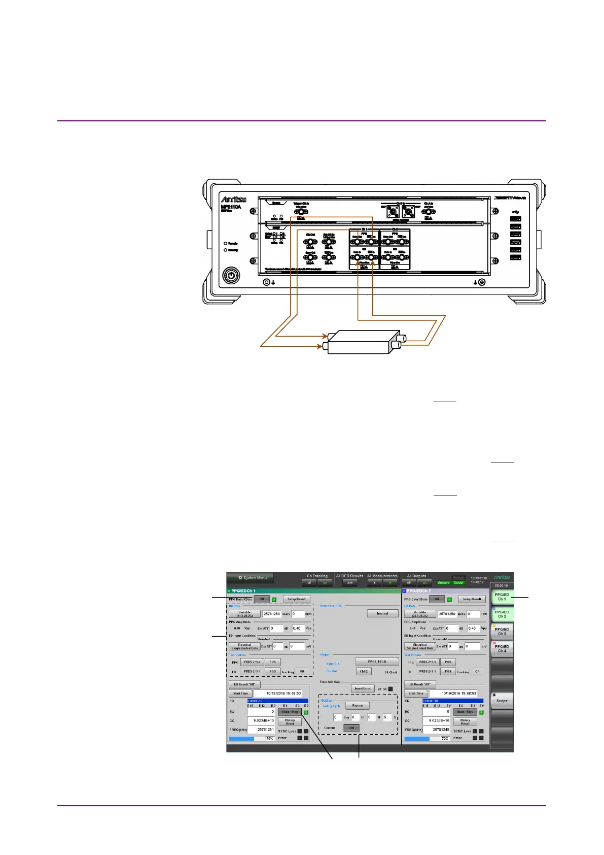
Figure 3.1-1 Making Connections Using Electrical Signal
1. Connect the DUT input connectors to PPG1
Out
and
Data Out
connectors using the coaxial cables.
If the DUT has only one input connector, connect it to the
Data
Out
connector of PPG1. Also, connect the coaxial terminator, which is
attached to the MP2110A standard configuration, to the
Out
connector.
2. Connect the DUT output connectors to ED1
In
and
Data In
connectors using the coaxial cables.
If the DUT has only one output connector, connect it to the
Data In
connector of ED1. Also, connect the supplied open to the
In
connector.
Figure 3.1-2 User Interfaces Used For Measuring Bit Error Rate
(Numbers Shown Correspond to Step Numbers.)